Nissan Pathfinder (2005 year). Manual - part 222


  Index      Manuals     Nissan Pathfinder (2005 year) - Service and Repair Manual


Search            copyright infringement  


Content      ..     220      221      222      223     ..


Nissan Pathfinder (2005 year). Manual - part 222


DTC P1805 BRAKE SWITCH

EC-627

C

D

E

F

G

H

I

J

K

L

M

A

EC

2005 Pathfinder

Specification data are reference values and are measured between each terminal and ground.

CAUTION:

Do not use ECM ground terminals when measuring input/output voltage. Doing so may result in dam-
age to the ECM's transistor. Use a ground other than ECM terminals, such as the ground.

Diagnostic Procedure

UBS00KGX

1.

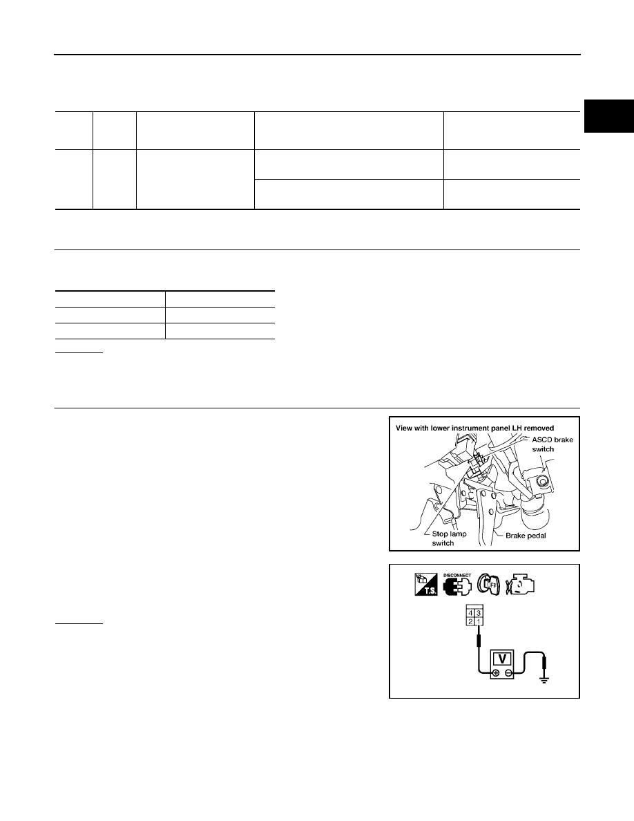
CHECK STOP LAMP SWITCH CIRCUIT

1.

Turn ignition switch OFF.

2.

Check the stop lamp when depressing and releasing the brake pedal.

OK or NG

OK

>> GO TO 4.

NG

>> GO TO 2.

2.

CHECK STOP LAMP SWITCH POWER SUPPLY CIRCUIT

1.

Disconnect stop lamp switch harness connector.

2.

Check voltage between stop lamp switch terminal 1 and ground
with CONSULT-II or tester.

OK or NG

OK

>> GO TO 4.

NG

>> GO TO 3.

TER-

MINAL

NO.

WIRE

COLOR

ITEM

CONDITION

DATA (DC Voltage)

101

LG

Stop lamp switch

[Ignition switch: OFF]

Brake pedal: Fully released

Approximately 0V

[Ignition switch: OFF]

Brake pedal: Slightly depressed

BATTERY VOLTAGE
(11 - 14V)

Brake pedal

Stop lamp

Fully released

Not illuminated

Slightly depressed

Illuminated

BBIA0560E

Voltage: Battery voltage

PBIB1184E

EC-628

DTC P1805 BRAKE SWITCH

2005 Pathfinder

3.

DETECT MALFUNCTIONING PART

Check the following.

10A fuse

Fuse block (J/B) connector E160

Harness for open and short between stop lamp switch and battery

>> Repair open circuit or short to ground or short to power in harness or connectors.

4.

CHECK STOP LAMP SWITCH INPUT SIGNAL CIRCUIT FOR OPEN AND SHORT

1.

Disconnect ECM harness connector.

2.

Disconnect stop lamp switch harness connector.

3.

Check harness continuity between ECM terminal 101 and stop
lamp switch terminal 2.
Refer to Wiring Diagram.

4.

Also check harness for short to ground and short to power.

OK or NG

OK

>> GO TO 5.

NG

>> Repair open circuit or short to ground or short to power

in harness or connectors.

5.

CHECK STOP LAMP SWITCH

Refer to

EC-629, "Component Inspection"

.

OK or NG

OK

>> GO TO 6.

NG

>> Replace stop lamp switch.

6.

CHECK INTERMITTENT INCIDENT

Refer to

EC-158, "TROUBLE DIAGNOSIS FOR INTERMITTENT INCIDENT"

.

>> INSPECTION END

Continuity should exist.

BBIA0560E

DTC P1805 BRAKE SWITCH

EC-629

C

D

E

F

G

H

I

J

K

L

M

A

EC

2005 Pathfinder

Component Inspection

UBS00KGY

STOP LAMP SWITCH

1.

Disconnect stop lamp switch harness connector.

2.

Check continuity between stop lamp switch terminals 1 and 2
under the following conditions.

3.

If NG, adjust stop lamp switch installation, refer to

BR-6,

"BRAKE PEDAL"

, and perform step 2 again.

BBIA0560E

Conditions

Continuity

Brake pedal fully released

Should not exist.

Brake pedal slightly depressed

Should exist.

PBIB1185E

EC-630

DTC P2122, P2123 APP SENSOR

2005 Pathfinder

DTC P2122, P2123 APP SENSOR

PFP:18002

Component Description

UBS00KGZ

The accelerator pedal position sensor is installed on the upper end
of the accelerator pedal assembly. The sensor detects the accelera-
tor position and sends a signal to the ECM.
Accelerator pedal position sensor has two sensors. These sensors
are a kind of potentiometers which transform the accelerator pedal
position into output voltage, and emit the voltage signal to the ECM.
In addition, these sensors detect the opening and closing speed of
the accelerator pedal and feed the voltage signals to the ECM. The
ECM judges the current opening angle of the accelerator pedal from
these signals and controls the throttle control motor based on these
signals.
Idle position of the accelerator pedal is determined by the ECM
receiving the signal from the accelerator pedal position sensor. The ECM uses this signal for the engine oper-
ation such as fuel cut.

CONSULT-II Reference Value in Data Monitor Mode

UBS00KH0

Specification data are reference values.

*: Accelerator pedal position sensor 2 signal is converted by ECM internally. Thus, it differs from ECM terminal voltage.

On Board Diagnosis Logic

UBS00KH1

These self-diagnoses have the one trip detection logic.

NOTE:
If DTC P2122 or P2123 is displayed with DTC P1229, first perform the trouble diagnosis for DTC P1229.
Refer to

EC-478, "DTC P1229 SENSOR POWER SUPPLY"

.

FAIL-SAFE MODE

When the malfunction is detected, ECM enters fail-safe mode and the MIL lights up.

PBIB1741E

MONITOR ITEM

CONDITION

SPECIFICATION

ACCEL SEN 1

Ignition switch: ON
(Engine stopped)

Accelerator pedal: Fully released

0.65 - 0.87V

Accelerator pedal: Fully depressed

More than 4.3V

ACCEL SEN 2*

Ignition switch: ON
(Engine stopped)

Accelerator pedal: Fully released

0.56 - 0.96V

Accelerator pedal: Fully depressed

More than 4.0V

CLSD THL POS

Ignition switch: ON
(Engine stopped)

Accelerator pedal: Fully released

ON

Accelerator pedal: Slightly depressed

OFF

DTC No.

Trouble diagnosis name

DTC detecting condition

Possible cause

P2122
2122

Accelerator pedal posi-
tion sensor 1 circuit low
input

An excessively low voltage from the APP sen-
sor 1 is sent to ECM.

Harness or connectors
(The APP sensor 1 circuit is open or
shorted.)

Accelerator pedal position sensor
(Accelerator pedal position sensor 1)

P2123
2123

Accelerator pedal posi-
tion sensor 1 circuit high
input

An excessively high voltage from the APP sen-
sor 1 is sent to ECM.

Engine operating condition in fail-safe mode

The ECM controls the electric throttle control actuator in regulating the throttle opening in order for the idle position to be within +10
degrees.
The ECM regulates the opening speed of the throttle valve to be slower than the normal condition.
So, the acceleration will be poor.

DTC P2122, P2123 APP SENSOR

EC-631

C

D

E

F

G

H

I

J

K

L

M

A

EC

2005 Pathfinder

DTC Confirmation Procedure

UBS00KH2

NOTE:
If DTC Confirmation Procedure has been previously conducted, always turn ignition switch OFF and wait at
least 10 seconds before conducting the next test.
TESTING CONDITION:
Before performing the following procedure, confirm that battery voltage is more than 10V at idle.

WITH CONSULT-II

1.

Turn ignition switch ON.

2.

Select “DATA MONITOR” mode with CONSULT-II.

3.

Start engine and let it idle for 1 second.

4.

If DTC is detected, go to

EC-633, "Diagnostic Procedure"

.

WITH GST

Follow the procedure “WITH CONSULT-II” above.

SEF058Y

EC-632

DTC P2122, P2123 APP SENSOR

2005 Pathfinder

Wiring Diagram

UBS00KH3

BBWA1747E

DTC P2122, P2123 APP SENSOR

EC-633

C

D

E

F

G

H

I

J

K

L

M

A

EC

2005 Pathfinder

Specification data are reference values and are measured between each terminal and ground.

CAUTION:

Do not use ECM ground terminals when measuring input/output voltage. Doing so may result in dam-
age to the ECM's transistor. Use a ground other than ECM terminals, such as the ground.

Diagnostic Procedure

UBS00KH4

1.

CHECK GROUND CONNECTIONS

1.

Turn ignition switch OFF.

2.

Loosen and retighten three ground screws on the body. Refer to

EC-165, "Ground Inspection"

.

OK or NG

OK

>> GO TO 2.

NG

>> Repair or replace ground connections.

TER-

MINAL

NO.

WIRE

COLOR

ITEM

CONDITION

DATA (DC Voltage)

82

B

Sensor ground
(APP sensor 1)

[Engine is running]

Warm-up condition

Idle speed

Approximately 0V

83

GR

Sensor ground
(APP sensor 2)

[Engine is running]

Warm-up condition

Idle speed

Approximately 0V

90

L

Sensor power supply
(APP sensor 1)

[Ignition switch: ON]

Approximately 5V

91

G

Sensor power supply
(APP sensor 2)

[Ignition switch: ON]

Approximately 5V

98

GR

Accelerator pedal position
sensor 2

[Ignition switch: ON]

Engine: Stopped

Accelerator pedal: Fully released

0.28 - 0.48V

[Ignition switch: ON]

Engine: Stopped

Accelerator pedal: Fully depressed

More than 2.0V

106

R

Accelerator pedal position
sensor 1

[Ignition switch: ON]

Engine: Stopped

Accelerator pedal: Fully released

0.65 - 0.87V

[Ignition switch: ON]

Engine: Stopped

Accelerator pedal: Fully depressed

More than 4.3V

BBIA0539E

EC-634

DTC P2122, P2123 APP SENSOR

2005 Pathfinder

2.

CHECK APP SENSOR 1 POWER SUPPLY CIRCUIT

1.

Disconnect accelerator pedal position (APP) sensor harness connector.

2.

Turn ignition switch ON.

3.

Check voltage between APP sensor terminal 2 and ground with
CONSULT-II or tester.

OK or NG

OK

>> GO TO 3.

NG

>> Repair open circuit or short to ground or short to power

in harness or connectors.

3.

CHECK APP SENSOR 1 GROUND CIRCUIT FOR OPEN AND SHORT

1.

Turn ignition switch OFF.

2.

Disconnect ECM harness connector.

3.

Check harness continuity between APP sensor terminal 4 and ECM terminal 82.
Refer to Wiring Diagram.

4.

Also check harness for short to ground and short to power.

OK or NG

OK

>> GO TO 4.

NG

>> Repair open circuit or short to ground or short to power in harness or connectors.

4.

CHECK APP SENSOR INPUT SIGNAL CIRCUIT FOR OPEN AND SHORT

1.

Check harness continuity between ECM terminal 106 and APP sensor terminal 3.
Refer to Wiring Diagram.

2.

Also check harness for short to ground and short to power.

OK or NG

OK

>> GO TO 5.

NG

>> Repair open circuit or short to ground or short to power in harness or connectors.

5.

CHECK APP SENSOR

Refer to

EC-635, "Component Inspection"

.

OK or NG

OK

>> GO TO 7.

NG

>> GO TO 6.

Voltage: Approximately 5V

BBIA0556E

PBIB2608E

Continuity should exist.

Continuity should exist.


Content      ..     220      221      222      223     ..