Nissan Pathfinder (2005 year). Manual - part 193
DTC P0550 PSP SENSOR
EC-395
C
D
E
F
G
H
I
J
K
L
M
A
EC
2005 Pathfinder
6.
CHECK INTERMITTENT INCIDENT
Refer to
EC-158, "TROUBLE DIAGNOSIS FOR INTERMITTENT INCIDENT"
.
>> INSPECTION END
Component Inspection
UBS00KBA
POWER STEERING PRESSURE SENSOR
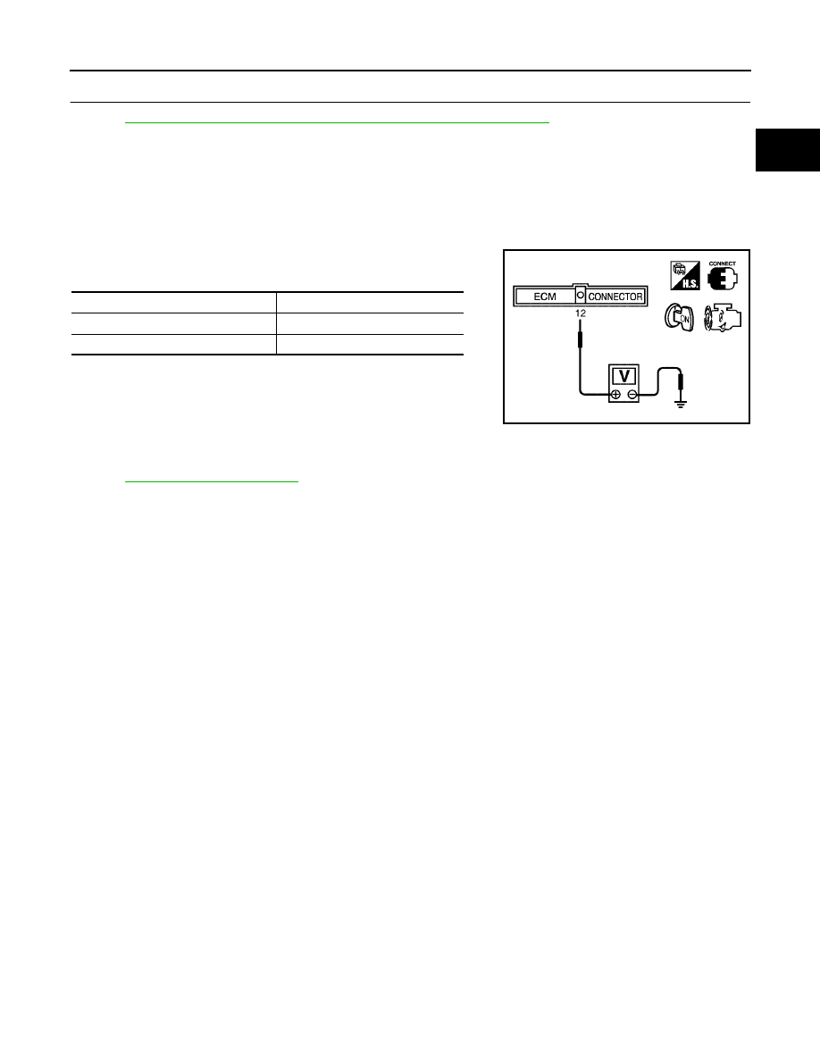
1.
Reconnect all harness connectors disconnected.
2.
Start engine and let it idle.
3.
Check voltage between ECM terminal 12 and ground under the
following conditions.
Removal and Installation
UBS00KBB
POWER STEERING PRESSURE SENSOR
Refer to
.
Condition
Voltage
Steering wheel is being turned.
0.5 - 4.5V
Steering wheel is not being turned.
0.4 - 0.8V
MBIB0126E