Nissan Pathfinder (2005 year). Manual - part 192
DTC P0506 ISC SYSTEM
EC-387
C
D
E
F
G
H
I
J
K
L
M
A
EC
2005 Pathfinder
DTC P0506 ISC SYSTEM
PFP:23781
Description
UBS00KAW
NOTE:
If DTC P0506 is displayed with other DTC, first perform the trouble diagnosis for the other DTC.
The ECM controls the engine idle speed to a specified level through the fine adjustment of the air, which is let
into the intake manifold, by operating the electric throttle control actuator. The operating of the throttle valve is
varied to allow for optimum control of the engine idling speed. The crankshaft position sensor (POS) detects
the actual engine speed and sends a signal to the ECM.
The ECM controls the electric throttle control actuator so that the engine speed coincides with the target value
memorized in the ECM. The target engine speed is the lowest speed at which the engine can operate steadily.
The optimum value stored in the ECM is determined by taking into consideration various engine conditions,
such as during warming up, deceleration, and engine load (air conditioner, power steering and cooling fan
operation, etc.).
On Board Diagnosis Logic
UBS00KAX
DTC Confirmation Procedure
UBS00KAY
NOTE:
●
If DTC Confirmation Procedure has been previously conducted, always turn ignition switch OFF and wait
at least 10 seconds before conducting the next test.
●
If the target idle speed is out of the specified value, perform,
EC-89, "Idle Air Volume Learning"
,
before conducting DTC Confirmation Procedure. For the target idle speed, refer to the
"SERVICE DATA AND SPECIFICATIONS (SDS)"
.
TESTING CONDITION:
●
Before performing the following procedure, confirm that battery voltage is more than 11V at idle.
●
Always perform the test at a temperature above
−
10
°
C (14
°
F).
WITH CONSULT-II
1.
Open engine hood.
2.
Start engine and warm it up to normal operating temperature.
3.
Turn ignition switch OFF and wait at least 10 seconds.
4.
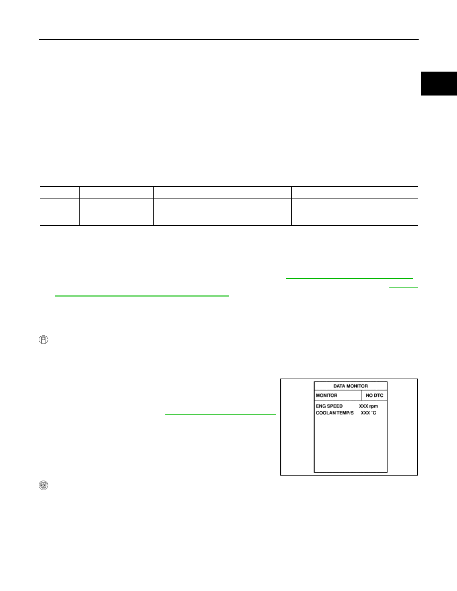
Turn ignition switch ON again and select “DATA MONITOR”
mode with CONSULT-II.
5.
Start engine and run it for at least 1 minute at idle speed.
6.
If 1st trip DTC is detected, go to
EC-388, "Diagnostic Procedure"
.
WITH GST
Follow the procedure “WITH CONSULT-II” above.
DTC No.
Trouble diagnosis name
DTC detecting condition
Possible cause
P0506
0506
Idle speed control sys-
tem RPM lower than
expected
The idle speed is less than the target idle
speed by 100 rpm or more.
●
Electric throttle control actuator
●
Intake air leak
SEF174Y