Nissan Pathfinder (2005 year). Manual - part 70


  Index      Manuals     Nissan Pathfinder (2005 year) - Service and Repair Manual


Search            copyright infringement  


Content      ..     68      69      70      71     ..


Nissan Pathfinder (2005 year). Manual - part 70


AUDIO

AV-35

C

D

E

F

G

H

I

J

L

M

A

B

AV

2005 Pathfinder

Steering Switch Check (With NAVI)

EKS009UB

1.

AV SWITCH SELF-DIAGNOSIS FUNCTION CHECK

1.

Start AV switch self-diagnosis function. Refer to

AV-29, "AV Switch Self-Diagnosis Function"

.

2.

Operate steering switch.

Does steering switch operate normally?

YES

>> Inspection End.

NO

>> GO TO 2.

2.

CHECK HARNESS

1.

Turn ignition switch OFF.

2.

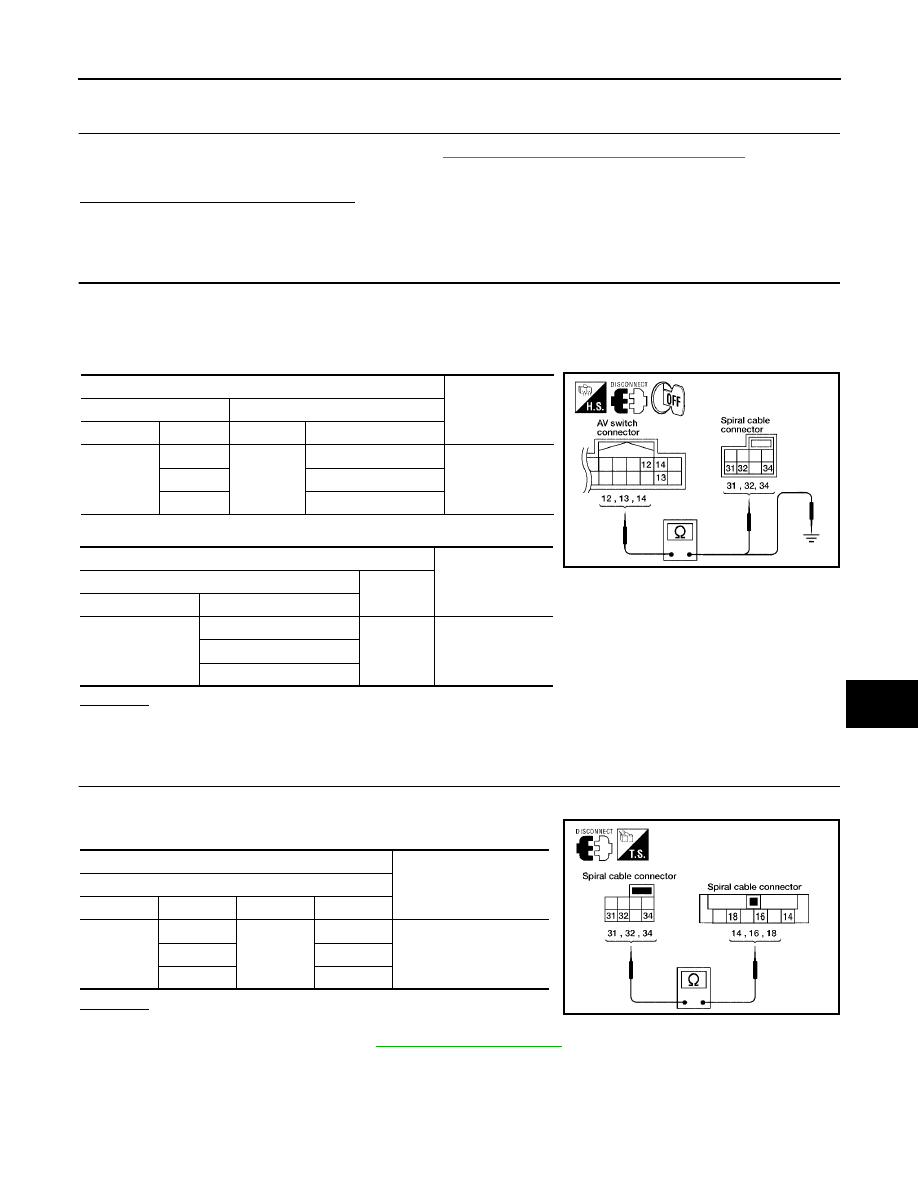
Disconnect AV switch connector M98 and spiral cable connector M30.

3.

Check continuity between spiral cable harness connector terminal and AV switch harness connector ter-
minal.

4.

Check continuity between AV switch and ground.

OK or NG

OK

>> GO TO 3.

NG

>> Repair harness.

3.

SPIRAL CABLE CHECK

1.

Disconnect spiral cable connectors M30 and M102.

2.

Check continuity between spiral cable terminals.

OK or NG

OK

>> GO TO 4.

NG

>> Replace spiral cable. Refer to

SRS-47, "SPIRAL CABLE"

.

Terminals

Continuity

Spiral cable

AV switch

Connector

Terminal

Connector

Terminal

M30

31

M98

13

Yes

32

14

34

12

Terminals

Continuity

AV switch

Connector

Terminal

M98

12

Ground

No

13

14

WKIA3232E

Terminals

Continuity

Spiral cable

Connector

Terminal

Connector

Terminal

M30

31

M102

18

Yes

32

16

34

14

WKIA3233E

AV-36

AUDIO

2005 Pathfinder

4.

CHECK STEERING SWITCH RESISTANCE

Check resistance between steering switch terminals.

OK or NG

OK

>> Inspection End.

NG

>> Replace steering switch. Refer to

AV-55, "Removal and Installation of Steering Wheel Audio Con-

trol Switches"

.

Steering Switch Check (Without NAVI)

EKS00D87

1.

CHECK HARNESS

1.

Turn ignition switch OFF.

2.

Disconnect audio unit connector M45 and spiral cable connector M30.

3.

Check continuity between spiral cable harness connector terminal and audio unit harness connector ter-
minal.

4.

Check continuity between audio unit and ground.

OK or NG

OK

>> GO TO 2.

NG

>> Repair harness.

Terminal

Signal name

Condition

Resistance

(

)

(Approx.)

18

16

Seek (down)

Depress (station) down switch.

165

Power

Depress power switch.

0

Volume (down)

Depress volume down switch.

652

14

16

Seek (up)

Depress (station) up switch.

165

Mode

Depress mode switch.

0

Volume (up)

Depress volume up switch.

652

WKIA3234E

Terminals

Continuity

Spiral cable

Audio unit

Connector

Terminal

Connector

Terminal

M30

31

M45

75

Yes

32

76

34

74

Terminals

Continuity

Audio unit

Connector

Terminal

M45

75

Ground

No

76

74

WKIA3235E

AUDIO

AV-37

C

D

E

F

G

H

I

J

L

M

A

B

AV

2005 Pathfinder

2.

SPIRAL CABLE CHECK

1.

Disconnect spiral cable connectors M30 and M102.

2.

Check continuity between spiral cable harness connector termi-
nals.

OK or NG

OK

>> GO TO 3.

NG

>> Replace spiral cable. Refer to

SRS-47, "SPIRAL CABLE"

.

3.

CHECK STEERING SWITCH RESISTANCE

Check resistance between steering switch terminals.

OK or NG

OK

>> Inspection End.

NG

>> Replace steering switch. Refer to

AV-55, "Removal and Installation of Steering Wheel Audio Con-

trol Switches"

.

AV Switch Check (With NAVI)

EKS00D88

1.

AV SWITCH SELF-DIAGNOSIS FUNCTION CHECK

Perform AV switch self-diagnosis function. Refer to

AV-29, "AV Switch Self-Diagnosis Function"

.

Does AV switch operate normally?

YES

>> Inspection End.

NO

>> GO TO 2.

2.

CHECK AV SWITCH POWER SUPPLY AND GROUND CIRCUIT

Check AV switch power supply and ground circuit. Refer to

AV-128, "Power Supply and Ground Circuit Check

for AV Switch"

.

OK or NG

OK

>> Replace AV switch. Refer to

AV-52, "Removal and Installation for AV Switch"

.

NG

>> Repair malfunctioning part.

Terminals

Continuity

Spiral cable

Connector

Terminal

Connector

Terminal

M30

31

M102

18

Yes

32

16

34

14

WKIA3233E

Terminal

Signal name

Condition

Resistance

(

)

(Approx.)

18

16

Seek (down)

Depress (station) down switch.

165

Power

Depress power switch.

0

Volume (down)

Depress volume down switch.

652

14

16

Seek (up)

Depress (station) up switch.

165

Mode

Depress mode switch.

0

Volume (up)

Depress volume up switch.

652

WKIA3234E

AV-38

AUDIO

2005 Pathfinder

Audio Communication Line Check (With Navigation System)

EKS009UD

1.

CHECK AUDIO COMMUNICATION LINE

Start audio communication line check. Refer to

AV-134, "Audio Communication Line Check (Between Display

Control Unit and Audio Unit)"

.

OK or NG

OK

>> Inspection End.

NG

>> Replace malfunctioning part.

Sound Is Not Heard From Front Door Speaker or Front Tweeter (Base and Mid
Level System)

EKS009UE

1.

HARNESS CHECK

1.

Disconnect audio unit connector M43 and suspect speaker or tweeter connector.

2.

Check continuity between audio unit harness connector M43 ter-
minal and suspect speaker or tweeter harness connector termi-
nal.

3.

Check continuity between audio unit harness connector M43 ter-
minal and ground.

OK or NG

OK

>> GO TO 2.

NG

>>

Check connector housings for disconnected or loose terminals.

Repair harness or connector.

Terminals

Continuity

Audio unit

Speaker or tweeter

Connector

Terminal

Connector

Terminal

M43

2

D12

+

Yes

1

-

4

D112

+

3

-

2

M109

+

1

-

4

M111

+

3

-

*: With mid-level system

Terminals

Continuity

Audio unit

Connector

Terminal

M43

2

Ground

No

1

4

3

WKIA1220E

AUDIO

AV-39

C

D

E

F

G

H

I

J

L

M

A

B

AV

2005 Pathfinder

2.

FRONT SPEAKER SIGNAL CHECK

1.

Connect audio unit connector and front speaker or tweeter connector.

2.

Turn ignition switch to ACC.

3.

Push “POWER” switch.

4.

Check the signal between audio unit harness connector terminal
and ground with CONSULT-II or oscilloscope.

OK or NG

OK

>> Replace speaker. Refer to

AV-52, "Removal and Instal-

lation of Speaker"

.

NG

>> Replace audio unit. Refer to

AV-52, "Removal and

Installation for Audio Unit"

.

Terminals

Condi-

tion

Reference

signal

(+)

(-)

Con-

nec-

tor

Termi-

nal

Con-

nec-

tor

Termi-

nal

M43

2

M43

1

Receive
audio
signal

4

3

SKIA4278E

SKIA0177E

AV-40

AUDIO

2005 Pathfinder

Sound Is Not Heard From Rear Door Speaker or Rear Door Tweeter (Base and
Mid Level System)

EKS009UF

1.

HARNESS CHECK

1.

Disconnect audio unit connector M44 and suspect speaker connector.

2.

Check continuity between audio unit harness connector M44 ter-
minal and suspect speaker harness connector terminal.

*: With mid level system.

3.

Check continuity between audio unit harness connector M44 ter-
minal and ground.

OK or NG

OK

>> GO TO 2.

NG

>>

Check connector housings for disconnected or loose terminals.

Repair harness or connector.

Terminals

Continuity

Audio unit

Speaker or tweeter

Connector

Terminal

Connector

Terminal

M44

13

D207

-

Yes

14

+

15

D307

-

16

+

13

D208*

-

14

+

15

D308*

-

16

+

Terminals

Continuity

Audio unit

Connector

Terminal

M44

13

Ground

No

14

15

16

WKIA1164E

AUDIO

AV-41

C

D

E

F

G

H

I

J

L

M

A

B

AV

2005 Pathfinder

2.

REAR SPEAKER SIGNAL CHECK

1.

Connect audio unit connector and rear speaker connector.

2.

Turn ignition switch to ACC.

3.

Push “POWER” switch.

4.

Check the signal between audio unit harness connector termi-
nals with CONSULT-II or oscilloscope.

OK or NG

OK

>> Replace rear door speaker. Refer to

AV-52, "Removal

and Installation of Speaker"

.

NG

>> Replace audio unit. Refer to

AV-52, "Removal and

Installation for Audio Unit"

.

Terminals

Condi-

tion

Reference

signal

(+)

(-)

Con-

nector

Termi-

nal

Con-

nector

Terminal

M44

14

M44

13

Receive
audio
signal

16

15

SKIA4281E

SKIA0177E

AV-42

AUDIO

2005 Pathfinder

Sound Is Not Heard From Front Door Speaker or Front Tweeter (BOSE System)

EKS009UG

1.

HARNESS CHECK

1.

Disconnect BOSE speaker amp. connector B75 and suspect speaker connector.

2.

Check continuity between BOSE speaker amp. harness connec-
tor terminal B75 and suspect speaker harness connector termi-
nal.

3.

Check continuity between BOSE speaker amp. harness connec-
tor terminal B75 and ground.

OK or NG

OK

>> GO TO 2.

NG

>>

Check connector housings for disconnected or loose terminals.

Repair harness or connector.

Terminals

Continuity

BOSE speaker amp.

Speaker or tweeter

Connector

Terminal

Connector

Terminal

B75

13

D12

+

Yes

14

-

15

D112

+

16

-

13

M109

+

14

-

15

M111

+

16

-

Terminals

Continuity

BOSE speaker amp.

Connector

Terminal

B75

13

Ground

No

14

15

16

WKIA2018E


Content      ..     68      69      70      71     ..