Nissan Pathfinder (2005 year). Manual - part 41
REPAIR FOR COMPONENT PARTS
AT-299
D
E
F
G
H
I
J
K
L
M
A
B
AT
2005 Pathfinder
ASSEMBLY
1.
Install drive plates, driven plates and retaining plate in direct clutch drum.
CAUTION:
Take care with order of plates.
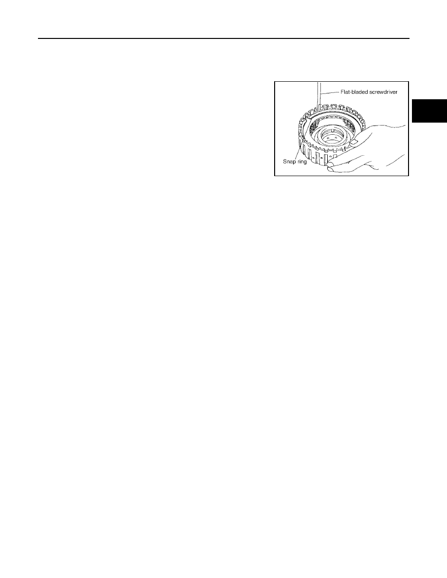
2.
Using a flat-bladed screwdriver, install snap ring in direct clutch
drum.
SCIA2868E