Nissan Pathfinder (2005 year). Manual - part 3
ADJUSTABLE PEDAL SYSTEM
AP-9
C
D
E
F
G
H
J
K
L
M
A
B
AP
2005 Pathfinder
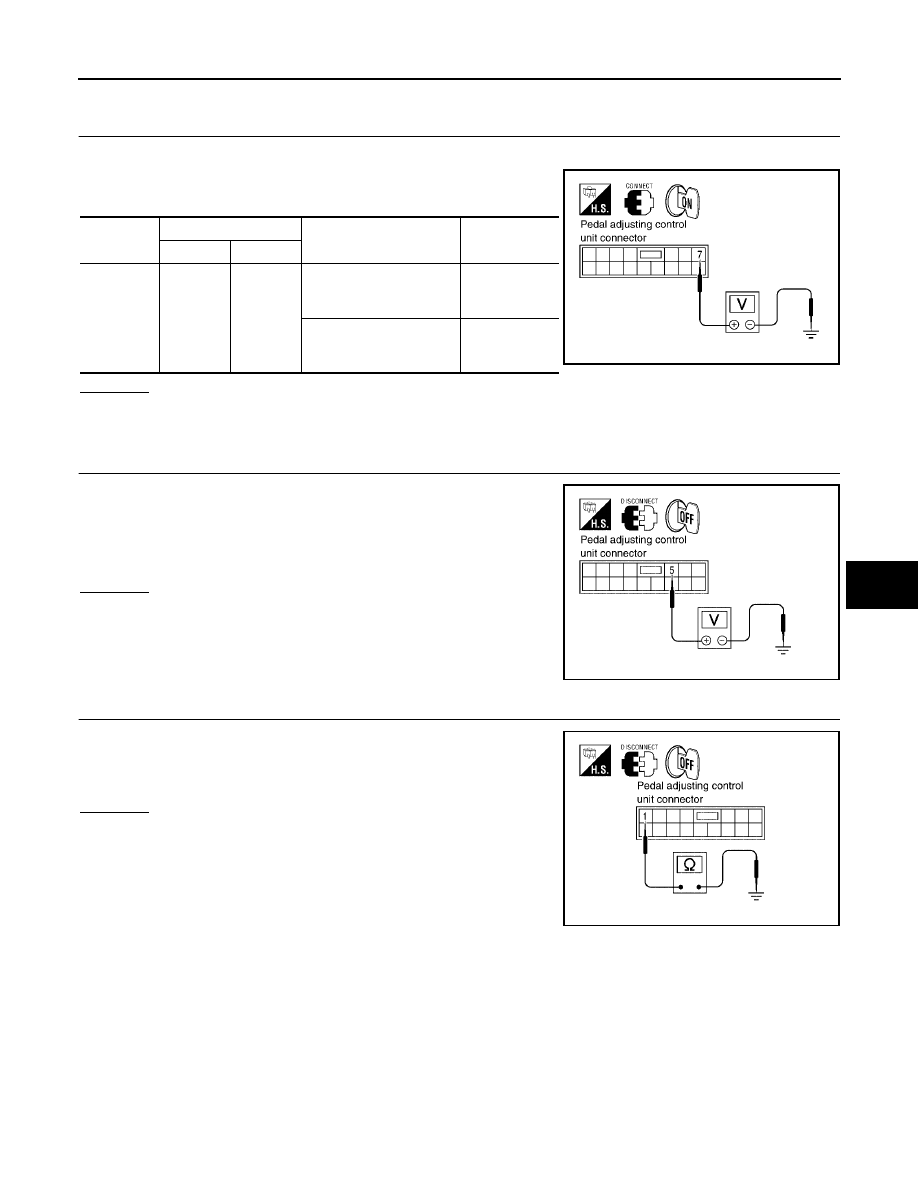
PEDAL ADJUSTING CONTROL UNIT POWER SUPPLY AND GROUND INSPECTION
1.
CHECK PEDAL ADJUSTING CONTROL UNIT OUTPUT POWER SUPPLY
1.
Turn ignition switch ON.
2.
Check voltage between pedal adjusting control unit connector
M14 terminal 7 and ground.
OK or NG
OK
>> Pedal adjusting control unit power supply and ground is OK.
NG
>> GO TO 2.
2.
CHECK PEDAL ADJUSTING CONTROL UNIT POWER SUPPLY CIRCUIT
1.
Disconnect pedal adjusting control unit.
2.
Check voltage between pedal adjusting control unit connector
M14 terminal 5 and ground.
OK or NG
OK
>> GO TO 3.
NG
>> Repair or replace the harness.
3.
CHECK PEDAL ADJUSTING CONTROL UNIT GROUND CIRCUIT
Check continuity between pedal adjusting control unit connector
M14 terminal 1 and ground.
OK or NG
OK
>> Replace pedal adjusting control unit.
NG
>> Repair or replace the harness.
Connector
Terminal (Wire color)
Condition
Voltage (V)
(Approx.)
(+)
(–)
M14
7
Ground
Ignition switch ON
A/T selector lever in P
position
Battery voltage
Ignition switch OFF
A/T selector lever in other
P position
0
LIIA2041E
5 - Ground
: Battery voltage
LIIA0887E
1 - Ground
: Continuity should exist.
LIIA0888E