Nissan Teana J32. Manual - part 998


  Index      Nissan     Nissan Teana J32 (2008 year) - Service and Repair Manual


Search            


Content   ..  996  997  998  999   ..


Nissan Teana J32. Manual - part 998


SQUEAK AND RATTLE TROUBLE DIAGNOSES

SE-125

< SYMPTOM DIAGNOSIS >

[WITHOUT VENTILATION SEAT]

C

D

E

F

G

H

I

K

L

M

A

B

SE

N

O

P

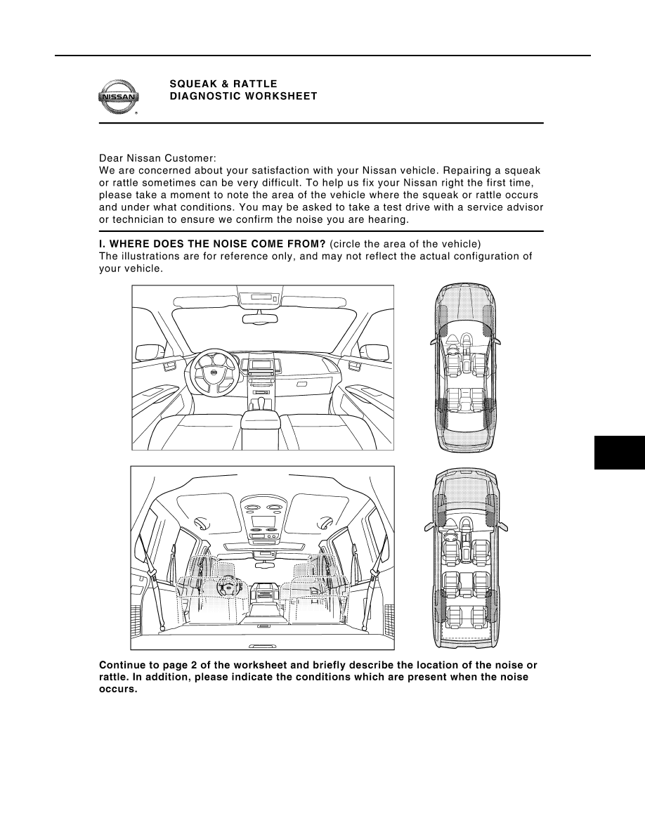
Diagnostic Worksheet

INFOID:0000000003940142

PIIB8740E

SE-126

< SYMPTOM DIAGNOSIS >

[WITHOUT VENTILATION SEAT]

SQUEAK AND RATTLE TROUBLE DIAGNOSES

PIIB8742E

PRECAUTIONS

SE-127

< PRECAUTION >

[WITHOUT VENTILATION SEAT]

C

D

E

F

G

H

I

K

L

M

A

B

SE

N

O

P

PRECAUTION

PRECAUTIONS

Precaution for Supplemental Restraint System (SRS) "AIR BAG" and "SEAT BELT 
PRE-TENSIONER"

INFOID:0000000003940150

The Supplemental Restraint System such as “AIR BAG” and “SEAT BELT PRE-TENSIONER”, used along
with a front seat belt, helps to reduce the risk or severity of injury to the driver and front passenger for certain
types of collision. Information necessary to service the system safely is included in the “SRS AIRBAG” and
“SEAT BELT” of this Service Manual.

WARNING:

• To avoid rendering the SRS inoperative, which could increase the risk of personal injury or death in

the event of a collision which would result in air bag inflation, all maintenance must be performed by
an authorized NISSAN/INFINITI dealer.

• Improper maintenance, including incorrect removal and installation of the SRS, can lead to personal

injury caused by unintentional activation of the system. For removal of Spiral Cable and Air Bag
Module, see the “SRS AIRBAG”.

• Never use electrical test equipment on any circuit related to the SRS unless instructed to in this Ser-

vice Manual. SRS wiring harnesses can be identified by yellow and/or orange harnesses or harness
connectors.

Precaution Necessary for Steering Wheel Rotation after Battery Disconnect

INFOID:0000000003885171

NOTE:
• Before removing and installing any control units, first turn the push-button ignition switch to the LOCK posi-

tion, then disconnect both battery cables.

• After finishing work, confirm that all control unit connectors are connected properly, then re-connect both

battery cables.

• Always use CONSULT-III to perform self-diagnosis as a part of each function inspection after finishing work.

If a DTC is detected, perform trouble diagnosis according to self-diagnosis results.

This vehicle is equipped with a push-button ignition switch and a steering lock unit.
If the battery is disconnected or discharged, the steering wheel will lock and cannot be turned.
If turning the steering wheel is required with the battery disconnected or discharged, follow the procedure
below before starting the repair operation.

OPERATION PROCEDURE

1.

Connect both battery cables.
NOTE:
Supply power using jumper cables if battery is discharged.

2.

Turn the push-button ignition switch to ACC position.
(At this time, the steering lock will be released.)

3.

Disconnect both battery cables. The steering lock will remain released with both battery cables discon-
nected and the steering wheel can be turned.

4.

Perform the necessary repair operation.

5.

When the repair work is completed, re-connect both battery cables. With the brake pedal released, turn
the push-button ignition switch from ACC position to ON position, then to LOCK position. (The steering
wheel will lock when the push-button ignition switch is turned to LOCK position.)

6.

Perform self-diagnosis check of all control units using CONSULT-III.

Service Notice

INFOID:0000000003840019

• When removing or installing various parts, place a cloth or padding onto the vehicle body to prevent

scratches.

• Handle trim, molding, instruments, grille, etc. carefully during removing or installing. Be careful not to oil or

damage them.

• Apply sealing compound where necessary when installing parts.
• When applying sealing compound, be careful that the sealing compound does not protrude from parts.

SE-128

< PRECAUTION >

[WITHOUT VENTILATION SEAT]

PRECAUTIONS

• When replacing any metal parts (for example body outer panel, members, etc.), be sure to take rust preven-

tion measures.

Precaution for Work

INFOID:0000000003840020

• When removing or disassembling each component, be careful not to damage or deform it. If a component

may be subject to interference, be sure to protect it with a shop cloth.

• When removing (disengaging) components with a screwdriver or similar tool, be sure to wrap the component

with a shop cloth or vinyl tape to protect it.

• Protect the removed parts with a shop cloth and keep them.
• Replace a deformed or damaged clip.
• If a part is specified as a non-reusable part, always replace it with new one.
• Be sure to tighten bolts and nuts securely to the specified torque.
• After re-installation is completed, be sure to check that each part works normally.
• Follow the steps below to clean components.
- Water soluble foul: Dip a soft cloth into lukewarm water, and wring the water out of the cloth to wipe the

fouled area.
Then rub with a soft and dry cloth.

- Oily foul: Dip a soft cloth into lukewarm water with mild detergent (concentration: within 2 to 3%), and wipe

the fouled area.
Then dip a cloth into fresh water, and wring the water out of the cloth to wipe the detergent off. Then rub with
a soft and dry cloth.

• Never use organic solvent such as thinner, benzene, alcohol, and gasoline.
• For genuine leather seats, use a genuine leather seat cleaner.


Content   ..  996  997  998  999   ..