Nissan Teana J32. Manual - part 969
HEATED SEAT
SE-9
< FUNCTION DIAGNOSIS >
[WITH VENTILATION SEAT]
C
D
E
F
G
H
I
K
L
M
A
B
SE
N
O
P
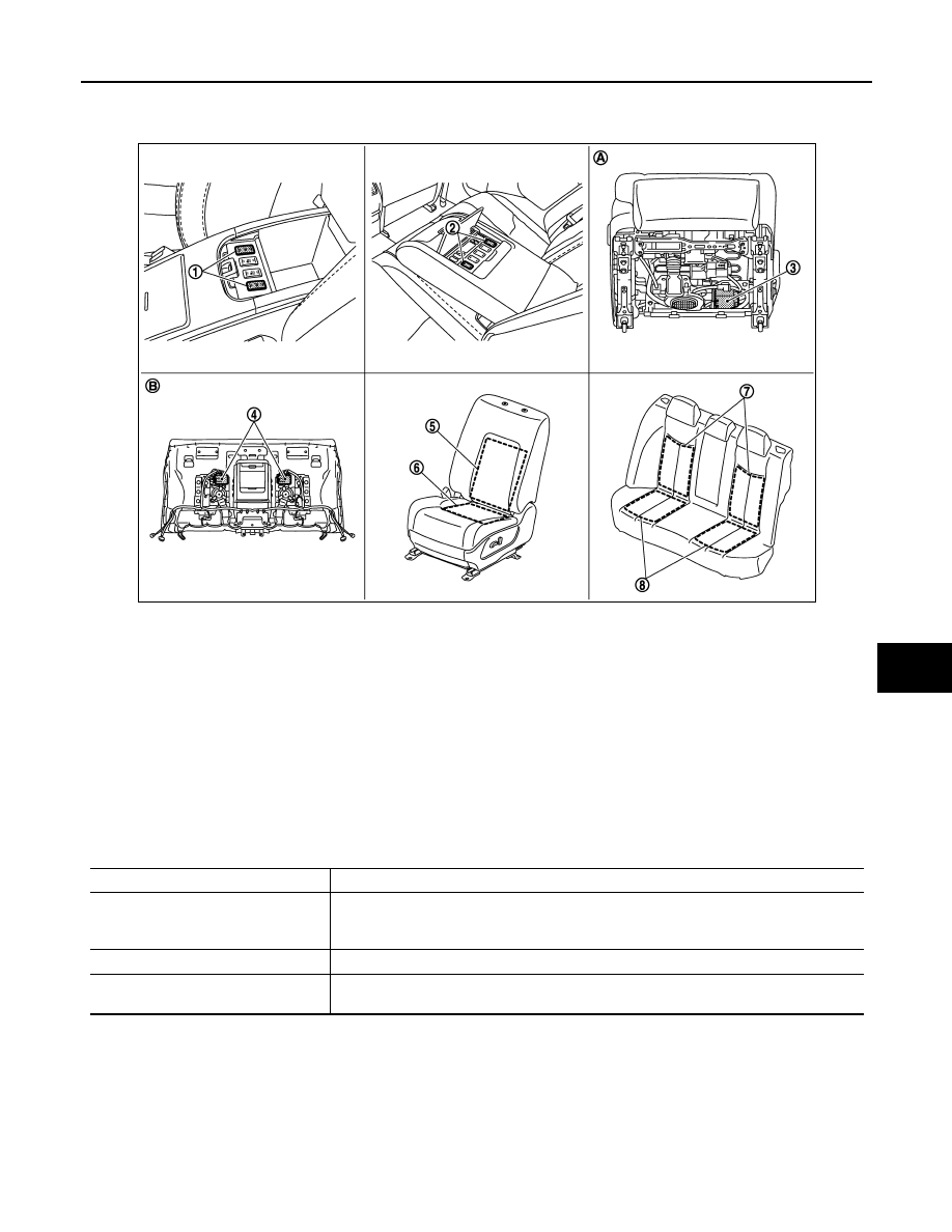
Component Parts Location
INFOID:0000000003820815
Component Description
INFOID:0000000003820816
1.
Front heated seat switch
• Driver side M206
• Passenger side M207
2.
Rear heated seat switch
• LH B494
• RH B505
3.
Front ventilation seat control unit
• Driver side B465, B466, B467
• Passenger side B441, B442, B443
4.
Rear ventilation seat control unit
• LH B489, B490, B491
• RH B500, B501, B502
5.
Front seatback heater
• Driver side B464
• Passenger side B433
6.
Front seat cushion heater
• Driver side B463
• Passenger side B432
7.
Rear seatback heater
• LH B488
• RH B499
8.
Rear seat cushion heater
• LH B487
• RH B498
A.
Backside of seat cushion (front seat) B.
Backside of seatback (rear seat)
JMJIA1840ZZ
Item
Function
Heated seat switch
• Switches the LO or HI temperature of the heated seat and turns OFF the heated seat
operation
• Illuminates the indicator that indicates the operating status of each mode
Heater unit
Warms the seat cushion and seatback
Ventilation seat control unit
Installed on each seat (driver seat, passenger seat, rear seat LH and RH) and controls the
heated seat and ventilation seat functions