Nissan Teana J32. Manual - part 850
PCS-6
< FUNCTION DIAGNOSIS >
[IPDM E/R]
RELAY CONTROL SYSTEM
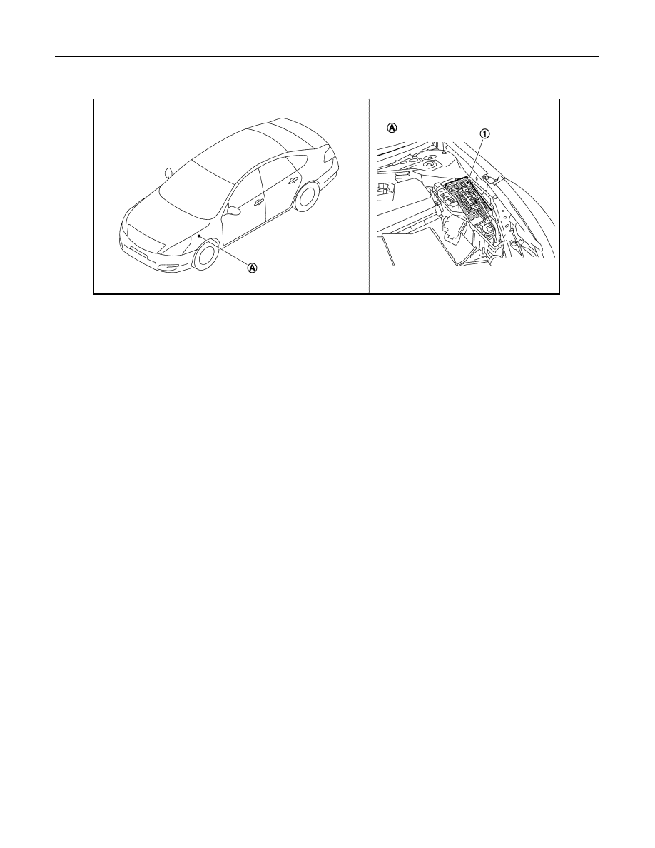
Component Parts Location
INFOID:0000000003773257
1.
IPDM E/R
A.
Engine room (LH)
JPMIA1037ZZ
|
|
|
PCS-6 < FUNCTION DIAGNOSIS > [IPDM E/R] RELAY CONTROL SYSTEM Component Parts Location INFOID:0000000003773257 1. IPDM E/R A. Engine room (LH) JPMIA1037ZZ |