Nissan Teana J32. Manual - part 848


  Index      Nissan     Nissan Teana J32 (2008 year) - Service and Repair Manual


Search            


Content   ..  846  847  848  849   ..


Nissan Teana J32. Manual - part 848


PB-8

< ON-VEHICLE REPAIR >

PARKING BRAKE SHOE

CAUTION:

The parking brake shoes for the front side are made of different materials from those for the rear
side. Never misidentify them when removing and replacing.

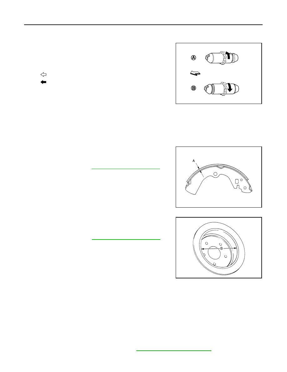
• Assemble adjusters so that threaded part is expanded when rotat-

ing it in the direction shown by arrow.

• Shorten adjuster by rotating it.
• When disassembling, apply PBC (Poly Butyl Cuprysil) grease or

silicone-based grease to threads.

• Check parking brake shoe sliding surface and drum inner surface

for grease. Wipe it off if it adhere on the surfaces.

Inspection and Adjustment

INFOID:0000000003811319

INSPECTION

Brake Lining Thickness Inspection

• Check thickness (A) of brake lining.

Drum Inner Diameter Inspection

• Check inner diameter (B) of drum. 

Other Inspections

• Check brake lining for excessive wear, damage, and peeling. Replace if necessary.
• Check parking brake shoe sliding surface for excessive wear and damage. Replace if necessary.
• Check anti-rattle pin and retainer for excessive wear, damage and rust. Replace if necessary.
• Check adjuster spring, anti-rattle spring and return springs for settling, excessive wear, damage, and rust.

Replace if necessary.

• Check adjuster for smoothness. Replace if necessary.
• Check toggle lever for excessive wear, damage and rust. Replace if necessary.
• Visually check inside of the drum for excessive wear, cracks, and damage with a pair of vernier calipers.

Replace if necessary.

ADJUSTMENT

1.

Adjust the parking brake pedal stroke. Refer to 

PB-2, "Inspection and Adjustment"

.

2.

Check a drag of the parking brake.

A

: For RH brake

B

: For LH brake

: Vehicle front

: Adjuster expands

JPFIB0009ZZ

Limit

A

: Refer to 

PB-10, "Parking Drum Brake"

.

SBR021A

Limit

B

: Refer to 

PB-10, "Parking Drum Brake"

.

JPFIB0008ZZ

PARKING BRAKE SHOE

PB-9

< ON-VEHICLE REPAIR >

C

D

E

G

H

I

J

K

L

M

A

B

PB

N

O

P

CAUTION:

If any drag is found, inspection the rear disc brake. Refer to 

BR-42, "BRAKE CALIPER ASSEMBLY

: Disassembly and Assembly"

.

PB-10

< SERVICE DATA AND SPECIFICATIONS (SDS) 

SERVICE DATA AND SPECIFICATIONS (SDS)

SERVICE DATA AND SPECIFICATIONS (SDS)

SERVICE DATA AND SPECIFICATIONS (SDS)

Parking Drum Brake

INFOID:0000000003811320

Unit: mm (in)

Parking Brake Control

INFOID:0000000003811321

Item

Limit

Brake lining

1.5 (0.059)

Drum (disc of inner diameter)

 172 (6.77)

Item

Standard

Number of notches [under force of 196 N (20 kg, 44 lb)]

6 – 7 notches

Number of notches when brake warning lamp turns ON

1 notch

PCS

PCS-1

ELECTRICAL & POWER CONTROL

C

D

E

F

G

H

I

J

K

L

B

SECTION 

PCS

A

O

P

N

CONTENTS

POWER CONTROL SYSTEM

IPDM E/R

FUNCTION DIAGNOSIS ...............................

4

RELAY CONTROL SYSTEM  ..............................

4

System Diagram ........................................................

4

System Description  ...................................................

4

Component Parts Location ........................................

6

POWER CONTROL SYSTEM  .............................

7

System Diagram ........................................................

7

System Description  ...................................................

7

Component Parts Location ........................................

7

SIGNAL BUFFER SYSTEM  ................................

8

System Diagram ........................................................

8

System Description  ...................................................

8

Component Parts Location ........................................

8

POWER CONSUMPTION CONTROL SYS-
TEM .....................................................................

9

System Diagram ........................................................

9

System Description  ...................................................

9

Component Parts Location ......................................

10

DIAGNOSIS SYSTEM (IPDM E/R) .....................

11

Diagnosis Description  .............................................

11

CONSULT-III Function (IPDM E/R) .........................

13

COMPONENT DIAGNOSIS  .........................

16

U1000 CAN COMM CIRCUIT .............................

16

Description ..............................................................

16

DTC Logic  ...............................................................

16

Diagnosis Procedure ...............................................

16

B2098 IGNITION RELAY ON STUCK  ...............

17

Description ..............................................................

17

DTC Logic  ...............................................................

17

Diagnosis Procedure ...............................................

17

B2099 IGNITION RELAY OFF STUCK ..............

18

Description ...............................................................

18

DTC Logic ................................................................

18

Diagnosis Procedure  ...............................................

18

POWER SUPPLY AND GROUND CIRCUIT  ....

19

Diagnosis Procedure  ...............................................

19

ECU DIAGNOSIS .........................................

20

IPDM E/R (INTELLIGENT POWER DISTRI-
BUTION MODULE ENGINE ROOM)  ................

20

Reference Value ......................................................

20

Wiring Diagram - IPDM E/R -  ..................................

28

Fail-safe ...................................................................

31

DTC Index ...............................................................

33

ON-VEHICLE REPAIR .................................

34

IPDM E/R (INTELLIGENT POWER DISTRI-
BUTION MODULE ENGINE ROOM)  ................

34

Exploded View .........................................................

34

Removal and Installation  .........................................

34

POWER DISTRIBUTION SYSTEM

BASIC INSPECTION  ...................................

35

DIAGNOSIS AND REPAIR WORKFLOW  ........

35

Work Flow ................................................................

35

FUNCTION DIAGNOSIS ..............................

38

POWER DISTRIBUTION SYSTEM  ...................

38

System Description ..................................................

38

Component Parts Location  ......................................

40

Component Description ..........................................

40

DIAGNOSIS SYSTEM (BCM)  ...........................

41

COMMON ITEM  .........................................................

41

COMMON ITEM : CONSULT-III Function (BCM - 
COMMON ITEM)  .....................................................

41

INTELLIGENT KEY ....................................................

42


Content   ..  846  847  848  849   ..