Nissan Teana J32. Manual - part 822


  Index      Nissan     Nissan Teana J32 (2008 year) - Service and Repair Manual


Search            


Content   ..  820  821  822  823   ..


Nissan Teana J32. Manual - part 822


MWI

METER SYSTEM

MWI-31

< FUNCTION DIAGNOSIS >

C

D

E

F

G

H

I

J

K

L

M

B

A

O

P

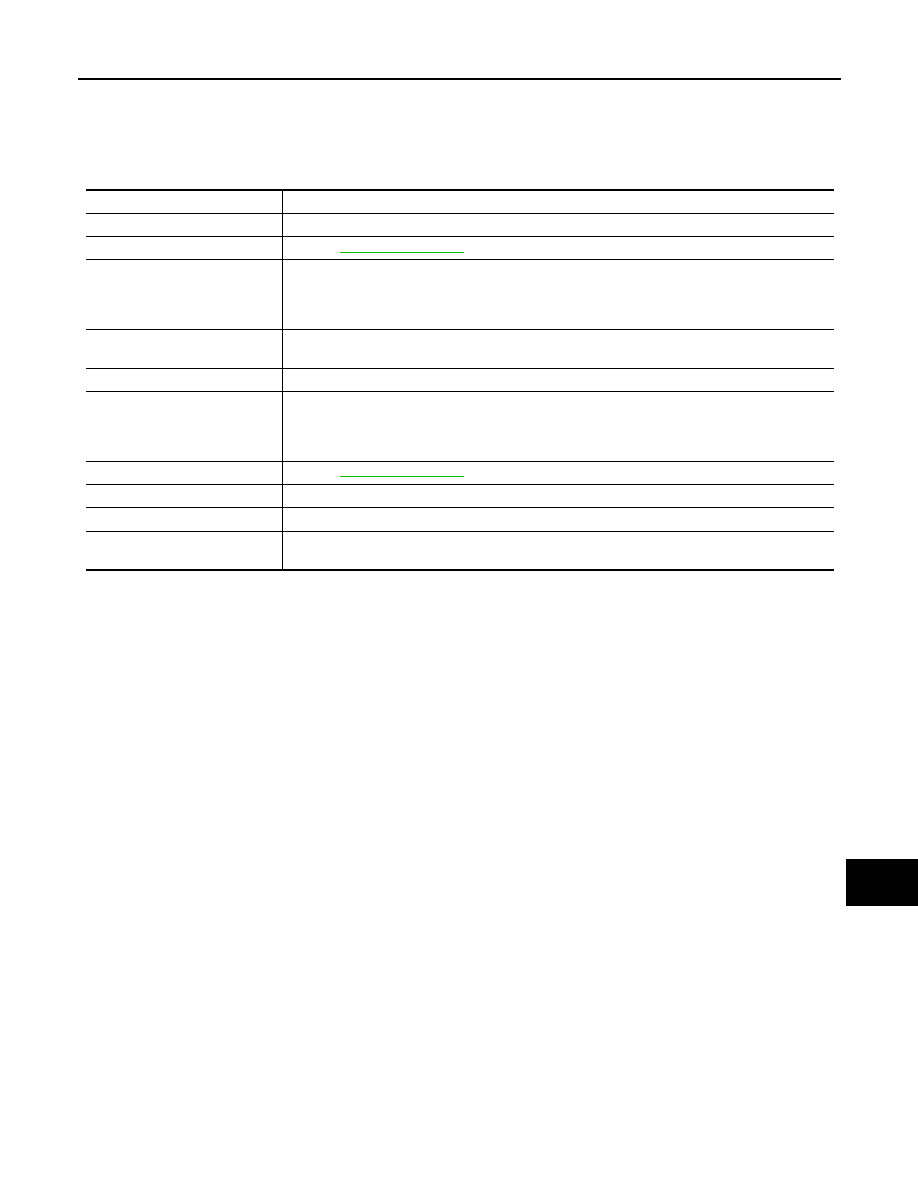
INFORMATION DISPLAY : Component Description

INFOID:0000000003792546

D.

Front bumper (left back)

E.

Engine room (LH)

F.

Behind the combination meter

G.

Lower left side of rear seat

Unit

Description

Combination meter

Controls the information display according to the signal received from each unit.

Fuel level sensor unit

Refer to 

MWI-45, "Description"

.

ECM

Transmits the following signals to the combination meter via CAN communication.

• Engine speed signal

• Fuel consumption monitor signal

ABS actuator and electric unit 
(control unit)

Transmits the vehicle speed signal to the combination meter via CAN communication.

BCM

Transmits signals provided by various units to the combination meter via CAN communication.

Meter control switch

Transmits the following signals to the combination meter.

• Enter switch signal

• Select switch signal

Parking brake switch

Refer to 

MWI-52, "Description"

.

Door switch

Transmits the door switch signals to BCM.

Trunk room lamp switch

Transmits the trunk room lamp switch signal to BCM

Ambient sensor

Detects the ambient air temperature and transmits the ambient sensor signal to the combination 
meter.

MWI-32

< FUNCTION DIAGNOSIS >

DIAGNOSIS SYSTEM (METER)

DIAGNOSIS SYSTEM (METER)

Diagnosis Description

INFOID:0000000003792550

SELF-DIAGNOSIS MODE

• Information display LCD segment operation can be checked in self-diagnosis mode.
• Meters/gauges can be checked in self-diagnosis mode.

OPERATION PROCEDURE

1.

Turn ignition switch ON, and switch the trip meter to “trip A” or “trip B”.
NOTE:
If the diagnosis function is activated with “trip A” displayed, the mileage on “trip A” is reset to “0000.0”.
(The same way for “trip B”.)

2.

Turn ignition switch OFF.

3.

While pressing the trip reset switch (1), turn ignition switch ON
again.

4.

Make sure that the trip meter displays “0000.0”.

5.

Press the trip reset switch at least 3 times. (Within 7 seconds
after the ignition switch is turned ON.)

6.

The unified meter control unit is turned to self-diagnosis mode.
• The segment dots of the information display LCD (1) blink

alternately. 

• Water temperature gauge and fuel gauge return to zero, simul-

taneously.

NOTE:
• Check combination meter power supply and ground circuit when the self-diagnosis mode of the combi-

nation meter does not start. Replace combination meter if abnormal.

• If any of the segments are not displayed, replace combination meter.

JPNIA1020ZZ

JPNIA0766ZZ

MWI

DIAGNOSIS SYSTEM (METER)

MWI-33

< FUNCTION DIAGNOSIS >

C

D

E

F

G

H

I

J

K

L

M

B

A

O

P

7.

Each meter activates by pressing the trip reset switch.

NOTE:
If any of the meters or gauges are not activated, replace combination meter.

CONSULT-III Function (METER/M&A)

INFOID:0000000003792551

CONSULT-III APPLICATION ITEMS

CONSULT-III can perform the following diagnosis modes via CAN communication and the combination meter.

SELF DIAG RESULT

Refer to 

MWI-67, "DTC Index"

.

DATA MONITOR

Display Item List

X: Applicable

JPNIA1019ZZ

System

Diagnosis mode

Description

METER/M&A

Self Diagnostic Result

The combination meter checks the conditions and displays memorized errors.

Data Monitor

Displays the combination meter input/output data in real time.

Special function

Lighting history of the warning lamp and indicator lamp can be checked.

Display item [Unit]

MAIN

SIGNALS

Description

SPEED METER
[km/h]

X

Value of vehicle speed signal received from ABS actuator and electric unit (control 
unit) via CAN communication.
NOTE:
655.35 is displayed when the malfunction signal is received.

SPEED OUTPUT
[km/h]

X

Vehicle speed signal value transmitted to other units via CAN communication.
NOTE:
655.35 is displayed when the malfunction signal is received.

ODO OUTPUT
[km/h or mph]

Odometer signal value transmitted to other units via CAN communication.

TACHO METER
[rpm]

X

Value of the engine speed signal received from ECM via CAN communication.
NOTE:
8191.875 is displayed when the malfunction signal is received.

FUEL METER
[lit.]

X

Fuel level indicated on combination meter.

MWI-34

< FUNCTION DIAGNOSIS >

DIAGNOSIS SYSTEM (METER)

W TEMP METER
[

°

C] 

X

Value of engine coolant temperature signal is received from ECM via CAN com-
munication. 
NOTE:
215 is displayed when the malfunction signal is input.

ABS W/L
[On/Off]

Status of ABS warning lamp detected from ABS warning lamp signal is received 
from ABS actuator and electric unit (control unit) via CAN communication.

VDC/TCS IND
[On/Off]

Status of VDC OFF indicator lamp detected from VDC OFF indicator lamp signal 
is received from ABS actuator and electric unit (control unit) via CAN communica-
tion.

SLIP IND
[On/Off]

Status of SLIP indicator lamp detected from slip indicator lamp signal received 
from ABS actuator and electric unit (control unit) via CAN communication.

BRAKE W/L
[On/Off]

Status of brake warning lamp detected from brake warning lamp signal is received 
from ABS actuator and electric unit (control unit) via CAN communication.
NOTE:
Displays “Off” if the brake warning lamp is illuminated when the valve check starts, 
the parking brake switch is turned ON or the brake fluid level switch is turned ON.

DOOR W/L
[On/Off]

Status of door warning detected from door switch signal received from BCM via 
CAN communication.

TRUNK/GLAS-H
[On/Off]

Status of trunk warning detected from trunk switch signal received from BCM via 
CAN communication.

HI-BEAM IND
[On/Off]

Status of high beam indicator lamp detected from high beam request signal is re-
ceived from BCM via CAN communication.

TURN IND
[On/Off]

Status of turn indicator lamp detected from turn indicator signal is received from 
BCM via CAN communication.

FR FOG IND
[On/Off]

Status of front fog light indicator lamp detected from front fog light request signal 
is received from BCM via CAN communication.

RR FOG IND
[On/Off]

Status of rear fog light indicator lamp detected from rear fog light request signal is 
received from BCM via CAN communication.

LIGHT IND
[On/Off]

Status of light indicator lamp detected from position light request signal is received 
from BCM via CAN communication.

OIL W/L
[On/Off]

Status of oil pressure warning lamp detected from oil pressure switch signal is re-
ceived from BCM via CAN communication.

MIL
[On/Off] 

Status of malfunction indicator lamp detected from malfunctioning indicator lamp 
signal is received from ECM via CAN communication.

CRUISE IND
[On/Off]

Status of CRUISE indicator detected from ASCD status signal is received from 
ECM via CAN communication.

SPORT IND
[On/Off]

Status of SPORT indicator detected from sport mode switch signal is received 
from control device.

4WD W/L
[On/Off]

This item is displayed, but cannot be monitored.

4WD LOCK IND
[On/Off]

This item is displayed, but cannot be monitored.

FUEL W/L
[On/Off]

Low-fuel warning lamp status detected by the identified fuel level.

WASHER W/L
[On/Off]

This item is displayed, but cannot be monitored.

KEY G/Y W/L
[On/Off]

Status of key warning lamp (G/Y) detected from key warning signal is received 
from BCM via CAN communication.

AFS OFF IND
[On/Off]

This item is displayed, but cannot be monitored.

LCD
[B&P N, B&P I, ID NG, ROTAT, SFT 
P, INSRT, BATT, NO KY,OUTKY, LK 
WN]

Displays status of Intelligent Key system warning detected from meter display sig-
nal is received from BCM via CAN communication.

Display item [Unit]

MAIN

SIGNALS

Description


Content   ..  820  821  822  823   ..