Nissan Teana J32. Manual - part 806
CHASSIS MAINTENANCE
MA-33
< ON-VEHICLE MAINTENANCE >
C
D
E
F
G
H
I
J
K
L
M
B
MA
N
O
A
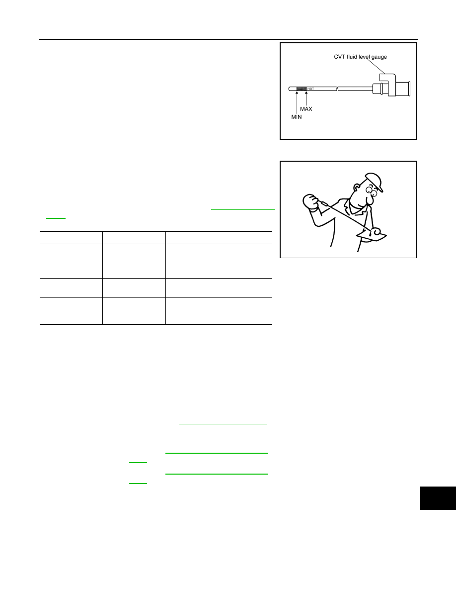
8.
Place the selector lever in “P” or “N” and check that the fluid
level is within the specified range.
CAUTION:
When reinstalling CVT fluid level gauge, insert it into the
CVT fluid charging pipe and rotate it to the original installa-
tion position until securely locked.
CVT FLUID CONDITION
Check CVT fluid condition.
• If CVT fluid is very dark or smells burned, check operation of CVT.
Flush cooling system after repair of CVT.
• If CVT fluid contains frictional material (clutches, brakes, etc.),
replace radiator and flush cooler line using cleaning solvent and
compressed air after repair of CVT. Refer to
.
CVT FLUID: RE0F10A : Changing
INFOID:0000000003862428
CAUTION:
Replace O-ring with new ones at the final stage of the operation when installing.
1.
Remove drain plug from oil pan.
2.
Remove drain plug gasket from drain plug.
3.
Install drain plug gasket to drain plug.
CAUTION:
Never reuse drain plug gasket.
4.
Install drain plug to oil pan. Refer to
.
5.
Fill CVT fluid from CVT fluid charging pipe to the specified level.
CAUTION:
• Use only Genuine NISSAN CVT Fluid NS-2. Never mix with other fluid.
• Using CVT fluid other than Genuine NISSAN CVT Fluid NS-2 will deteriorate in driveability and
CVT durability, and may damage the CVT, which is not covered by the warranty.
• When filling CVT fluid, take care not to scatter heat generating parts such as exhaust.
• Sufficiently shake the container of CVT fluid before using.
• Delete CVT fluid deterioration date with CONSULT-III after changing CVT fluid.
6.
With the engine warmed up, drive the vehicle in an urban area.
NOTE:
SCIA1932E
Fluid status
Conceivable cause
Required operation
Varnished (viscous
varnish state)
CVT fluid become
degraded due to
high temperatures.
Replace the CVT fluid and check the
CVT main unit and the vehicle for
malfunctions (wire harnesses, cool-
er pipes, etc.)
Milky white or
cloudy
Water in the fluid
Replace the CVT fluid and check for
places where water is getting in.
Large amount of
metal powder mixed
in
Unusual wear of
sliding parts within
CVT
Replace the CVT fluid and check for
improper operation of the CVT.
ATA0022D
CVT fluid
: Refer to
.
Fluid capacity
.