Nissan Teana J32. Manual - part 742


  Index      Nissan     Nissan Teana J32 (2008 year) - Service and Repair Manual


Search            


Content   ..  740  741  742  743   ..


Nissan Teana J32. Manual - part 742


INL-86

< ECU DIAGNOSIS >

BCM (BODY CONTROL MODULE)

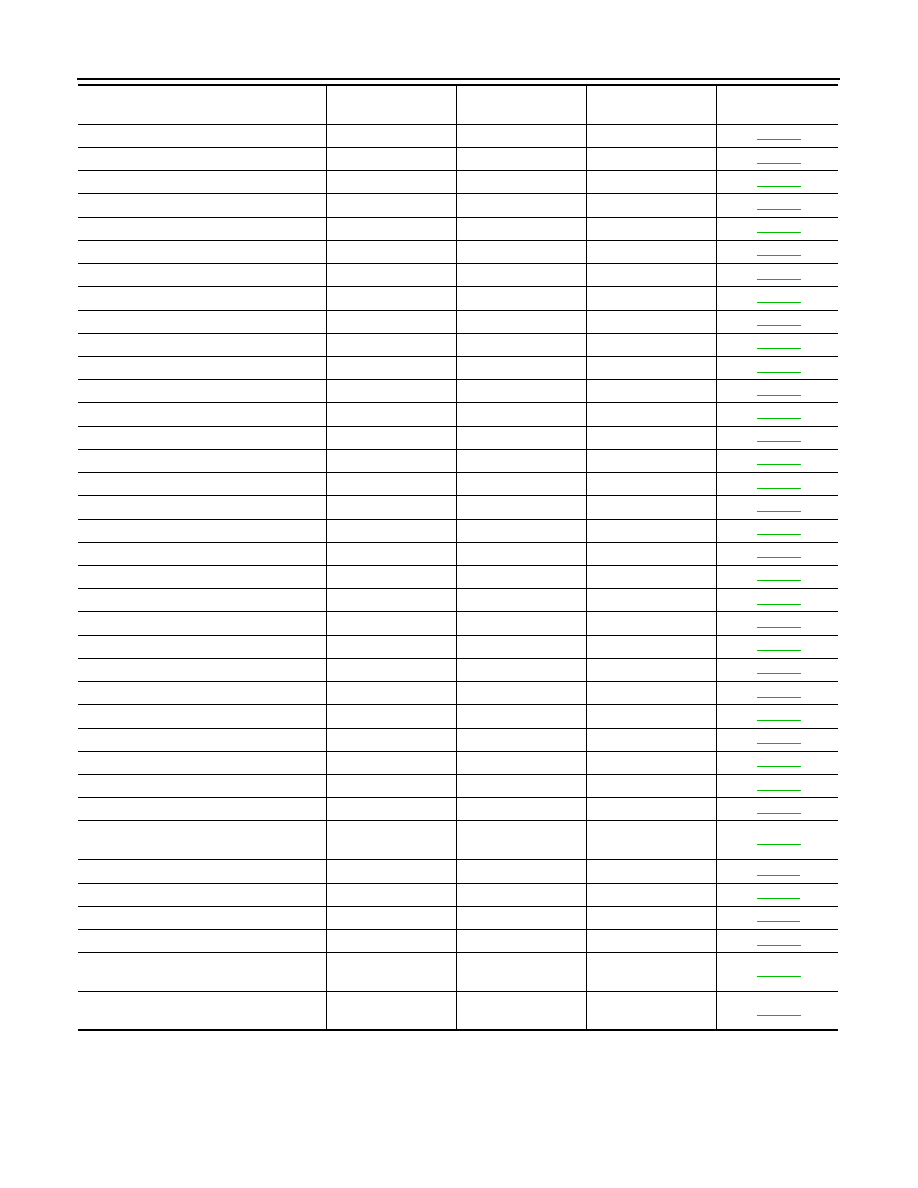
B2192: ID DISCORD BCM-ECM

×

SEC-43

B2193: CHAIN OF BCM-ECM

×

SEC-45

B2553: IGNITION RELAY

×

PCS-49

B2555: STOP LAMP

×

SEC-50

B2556: PUSH-BTN IGN SW

×

×

SEC-52

B2557: VEHICLE SPEED

×

×

×

SEC-54

B2560: STARTER CONT RELAY

×

×

×

SEC-55

B2562: LOW VOLTAGE

×

BCS-36

B2601: SHIFT POSITION

×

×

×

SEC-56

B2602: SHIFT POSITION

×

×

×

SEC-59

B2603: SHIFT POSI STATUS

×

×

×

SEC-61

B2604: PNP SW

×

×

×

SEC-64

B2605: PNP SW

×

×

×

SEC-67

B2606: S/L RELAY

×

×

×

SEC-69

B2607: S/L RELAY

×

×

×

SEC-70

B2608: STARTER RELAY

×

×

×

SEC-72

B2609: S/L STATUS

×

×

×

SEC-74

B260A: IGNITION RELAY

×

×

×

PCS-51

B260B: STEERING LOCK UNIT

×

×

SEC-78

B260C: STEERING LOCK UNIT

×

×

SEC-79

B260D: STEERING LOCK UNIT

×

×

SEC-80

B260F: ENG STATE SIG LOST

×

×

×

SEC-81

B2612: S/L STATUS

×

×

×

SEC-85

B2614: ACC RELAY CIRC

×

×

PCS-53

B2615: BLOWER RELAY CIRC

×

×

PCS-55

B2616: IGN RELAY CIRC

×

×

PCS-57

B2617: STARTER RELAY CIRC

×

×

×

SEC-89

B2618: BCM

×

×

×

PCS-59

B2619: BCM

×

×

×

SEC-91

B261A: PUSH-BTN IGN SW

×

×

SEC-92

B261E: VEHICLE TYPE

×

×

×

 (Turn ON for 15 

seconds)

SEC-95

B2621: INSIDE ANTENNA

×

DLK-50

B2622: INSIDE ANTENNA

×

DLK-52

B2623: INSIDE ANTENNA

×

DLK-54

B26E1: ENG STATE NO RES

×

×

×

SEC-82

B26E9: S/L STATUS

×

×

×

 (Turn ON for 15 

seconds)

SEC-83

B26EA: KEY REGISTRATION

×

×

 (Turn ON for 15 

seconds)

SEC-84

CONSULT display

Fail-safe

Freeze Frame Data

Intelligent Key warn-

ing lamp ON

Reference page

INTERIOR LIGHTING SYSTEM SYMPTOMS

INL-87

< SYMPTOM DIAGNOSIS >

C

D

E

F

G

H

I

J

K

M

A

B

INL

N

O

P

SYMPTOM DIAGNOSIS

INTERIOR LIGHTING SYSTEM SYMPTOMS

Symptom Table

INFOID:0000000003774578

CAUTION:

Perform the self-diagnosis with CONSULT-III before the symptom diagnosis. Perform the trouble diag-
nosis if any DTC is detected.

Symptom

Possible cause

Inspection item

All the following lamps are not turned ON.
• Map  lamp
• Personal  lamp
• Trunk room lamp
• Step  lamp
• Vanity mirror lamp

• Harness between BCM and each 

interior room lamp

• BCM

Interior room lamp power supply cir-
cuit
Refer to 

INL-20

.

• Interior room lamp is not 

turned ON even though 
the door is open.
(It turns ON when turning 
the interior room lamp 
ON.)

• Interior room lamp does 

not turn OFF even though 
the door is closed.

Map lamp and personal 
lamp

• Harness between BCM and each 

door switch

• Harness between BCM and map 

lamp

• BCM

Door switch circuit
Refer to 

DLK-57

.

Interior room lamp control circuit
Refer to 

INL-22

.

Only the map lamp

• Map lamp bulb
• Map lamp assembly

Only the personal lamp

• Personal lamp bulb
• Personal lamp assembly

Interior room lamp timer does not activate.
(It turns ON/OFF when the door opens/closes.)

Check the interior room lamp setting.
Refer to 

INL-16

.

Step lamps (driver side and passenger side) are not 
turned ON.
(Map lamp and personal lamp are turned ON.)

• Harness between BCM and each 

step lamp

• BCM

Step lamp circuit
Refer to 

INL-24

.

Step lamps (driver side and passenger side) are not 
turned OFF.
(Map lamp and personal lamp are turned OFF.)

• Trunk room lamp does not turn ON.

(The bulb is normal.)

• Trunk room lamp does not turn OFF.

• Harness between BCM and trunk 

room lamp switch

• Harness between BCM and trunk 

room lamp

• BCM

Trunk room lamp switch circuit
Refer to

DLK-70

.

Trunk room lamp circuit
Refer to 

INL-26

.

Push-button ignition switch illumination does not illu-
minate.

• Harness between BCM and push-

button ignition switch

• BCM

Push-button ignition switch illumina-
tion circuit
Refer to 

INL-28

.

Interior room lamp battery saver does not activate.

Check the interior room lamp battery 
saver setting.
Refer to 

INL-17

.

INL-88

< PRECAUTION >

PRECAUTIONS

PRECAUTION

PRECAUTIONS

Precaution for Supplemental Restraint System (SRS) "AIR BAG" and "SEAT BELT 
PRE-TENSIONER"

INFOID:0000000003813381

The Supplemental Restraint System such as “AIR BAG” and “SEAT BELT PRE-TENSIONER”, used along
with a front seat belt, helps to reduce the risk or severity of injury to the driver and front passenger for certain
types of collision. This system includes seat belt switch inputs and dual stage front air bag modules. The SRS
system uses the seat belt switches to determine the front air bag deployment, and may only deploy one front
air bag, depending on the severity of a collision and whether the front occupants are belted or unbelted.
Information necessary to service the system safely is included in the “SRS AIRBAG” and “SEAT BELT” of this
Service Manual.

WARNING:

• To avoid rendering the SRS inoperative, which could increase the risk of personal injury or death in

the event of a collision which would result in air bag inflation, all maintenance must be performed by
an authorized NISSAN/INFINITI dealer.

• Improper maintenance, including incorrect removal and installation of the SRS, can lead to personal

injury caused by unintentional activation of the system. For removal of Spiral Cable and Air Bag
Module, see the “SRS AIRBAG”.

• Do not use electrical test equipment on any circuit related to the SRS unless instructed to in this

Service Manual. SRS wiring harnesses can be identified by yellow and/or orange harnesses or har-
ness connectors.

MAP LAMP

INL-89

< ON-VEHICLE REPAIR >

C

D

E

F

G

H

I

J

K

M

A

B

INL

N

O

P

ON-VEHICLE REPAIR

MAP LAMP

Exploded View

INFOID:0000000003774581

NOTE:
After removing the headlining assembly, remove the map lamp assembly. Refer to 

INT-49, "NORMAL ROOF :

Exploded View"

.

Removal and Installation

INFOID:0000000003774582

After removing the headlining assembly, remove the map lamp assembly. Refer to 

INT-49, "NORMAL ROOF :

Exploded View"

.

Replacement

INFOID:0000000003774583

CAUTION:

• Disconnect the battery negative terminal or remove the fuse.
• Never touch the glass of bulb directly by hand. Keep grease and other oily matters away from it.

Never touch bulb by hand while it is lit or right after being turned off.

• Never leave bulb out of lamp reflector for a long time because dust, moisture smoke, etc. may affect

the performance of lamp. When replacing bulb, be sure to replace it with new one.

MAP LAMP BULB

1.

Insert any appropriate tool into the gap between the lens. Remove the lens.

2.

Remove the bulb.

1.

Map lamp assembly

2.

Bulb

3.

Lens

JPLIA0059ZZ


Content   ..  740  741  742  743   ..