Nissan Teana J32. Manual - part 726


  Index      Nissan     Nissan Teana J32 (2008 year) - Service and Repair Manual


Search            


Content   ..  724  725  726  727   ..


Nissan Teana J32. Manual - part 726


INL-22

< COMPONENT DIAGNOSIS >

INTERIOR ROOM LAMP CONTROL CIRCUIT

INTERIOR ROOM LAMP CONTROL CIRCUIT

Description

INFOID:0000000003774558

Controls each interior room lamp (ground side) by PWM signal.
NOTE:
PWM signal control period is approximately 250 Hz (in the gradual brightening/dimming).

Component Function Check

INFOID:0000000003774559

NOTE:
Replace the personal lamp assembly if the map lamp is turned ON but the personal lamp LH and RH are not
turn ON.

CAUTION:

 Before performing the diagnosis, check that the following is normal.
• Interior room lamp power supply
• Map lamp bulb
• Personal lamp bulb

1.

CHECK INTERIOR ROOM LAMP CONTROL FUNCTION

CONSULT-III ACTIVE TEST

1.

Switch the map lamp switch to DOOR.

2.

Turn ignition switch ON.

3.

Select “INT LAMP” of BCM (INT LAMP) active test item.

4.

With operating the test items, check that each interior room lamp turns ON/OFF (gradual brightening/dim-
ming).

Does the interior room lamp turns ON/OFF (gradual brightening/dimming)?

YES

>> Interior room lamp control circuit is normal.

NO

>> Refer to 

INL-22, "Diagnosis Procedure"

.

Diagnosis Procedure

INFOID:0000000003774560

1.

CHECK INTERIOR ROOM LAMP CONTROL OUTPUT

CONSULT-III ACTIVE TEST

1.

Turn ignition switch OFF.

2.

Remove all the bulbs of map lamp and personal lamp.

3.

Select “INT LAMP” of BCM (INT LAMP) active test item.

4.

 With operating the test item, check continuity between BCM harness connector and ground.

Is the measurement value normal?

YES

>> GO TO 2.

Fixed ON>>GO TO 3.
Fixed OFF>>Replace BCM.

2.

CHECK INTERIOR ROOM LAMP CONTROL OPEN CIRCUIT

1.

Turn ignition switch OFF.

2.

Disconnect BCM connector and map lamp connector.

3.

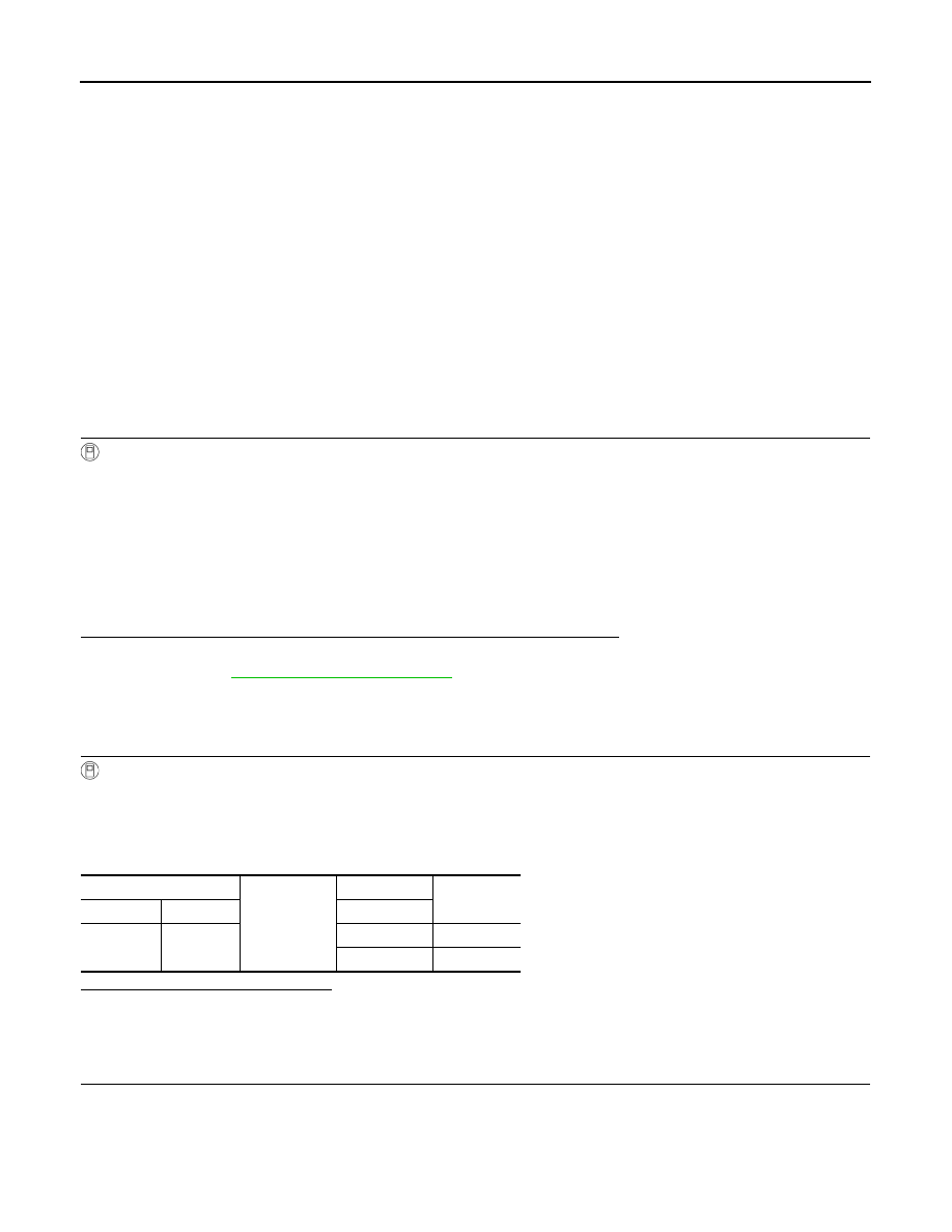
Check continuity between BCM harness connector and map lamp harness connector.

On

: Interior room lamp gradual brightening

Off

: Interior room lamp gradual dimming

BCM

Ground

Test item

Continuity

Connector

Terminal

INT LAMP

M119

19

On

Existed

Off

Not existed

INTERIOR ROOM LAMP CONTROL CIRCUIT

INL-23

< COMPONENT DIAGNOSIS >

C

D

E

F

G

H

I

J

K

M

A

B

INL

N

O

P

Does continuity exist?

YES

>> Replace the map lamp.

NO

>> Repair the harnesses or connectors.

3.

CHECK INTERIOR ROOM LAMP CONTROL SHORT CIRCUIT

1.

Turn ignition switch OFF.

2.

Disconnect BCM connector and map lamp connector.

3.

Check continuity between BCM harness connector and ground.

Does continuity exist?

YES

>> Repair the harnesses or connectors.

NO

>> Replace BCM.

BCM

Map lamp

Continuity

Connector

Terminal

Connector

Terminal

M119

19

R19

2

Existed

BCM

Ground

Continuity

Connector

Terminal

M119

19

Not existed

INL-24

< COMPONENT DIAGNOSIS >

STEP LAMP CIRCUIT

STEP LAMP CIRCUIT

Description

INFOID:0000000003774561

Controls the step lamp (ground side) to turn the step lamp ON and OFF.

Component Function Check

INFOID:0000000003774562

CAUTION:

 Before performing the diagnosis, check that the following is normal.
• Interior room lamp power supply
• Step lamp bulb

1.

CHECK STEP LAMP OPERATION

CONSULT-III ACTIVE TEST

1.

Turn ignition switch ON.

2.

Select "STEP LAMP TEST" of BCM (INT LAMP) active test item.

3.

With operating the test items, check that step lamp turns ON/OFF.

Does the step lamp turn ON/OFF?

YES

>> Step lamp circuit is normal.

NO

>> Refer to 

INL-24, "Diagnosis Procedure"

.

Diagnosis Procedure

INFOID:0000000003774563

1.

CHECK STEP LAMP OUTPUT

CONSULT-III ACTIVE TEST

1.

Turn ignition switch OFF.

2.

Remove the step lamp bulbs (driver side and passenger side).

3.

Turn ignition switch ON.

4.

Select “STEP LAMP TEST” of BCM (INT LAMP) active test item.

5.

 With operating the test item, check continuity between BCM harness connector and ground.

Is the measurement value normal?

YES

>> GO TO 2.

Fixed ON>>GO TO 3.
Fixed OFF>>Replace BCM.

2.

CHECK STEP LAMP OPEN CIRCUIT

1.

Turn ignition switch OFF.

2.

Disconnect BCM connector, and step lamp connector.

3.

Check continuity between BCM harness connector and step lamp harness connector.

On

: Step lamp ON

Off

: Step lamp OFF

BCM

Ground

Test item

Continuity

Connector

Terminal

STEP LAMP 

TEST

M119

7

On

Existed

Off

Not existed

STEP LAMP CIRCUIT

INL-25

< COMPONENT DIAGNOSIS >

C

D

E

F

G

H

I

J

K

M

A

B

INL

N

O

P

Does continuity exist?

YES

>> Replace step lamp.

NO

>> Repair harnesses or connectors.

3.

CHECK STEP LAMP SHORT CIRCUIT

1.

Turn ignition switch OFF.

2.

Check continuity between BCM harness connector and ground.

Does continuity exist?

YES

>> Repair the harnesses or connectors.

NO

>> Replace BCM.

BCM

Step lamp

Continuity

Connec-

tor

Terminal

Connector

Terminal

M119

7

Driver 
side

D17

2

Existed

Passen-
ger side

D51

2

BCM

Ground

Continuity

Connector

Terminal

M119

7

Not existed


Content   ..  724  725  726  727   ..