Nissan Teana J32. Manual - part 695


  Index      Nissan     Nissan Teana J32 (2008 year) - Service and Repair Manual


Search            


Content   ..  693  694  695  696   ..


Nissan Teana J32. Manual - part 695


INTAKE DOOR CONTROL SYSTEM

HAC-149

< FUNCTION DIAGNOSIS >

[WITH 7 INCH DISPLAY]

C

D

E

F

G

H

J

K

L

M

A

B

HAC

N

O

P

INTAKE DOOR CONTROL SYSTEM

WITHOUT INTELLIGENT AIR CONDITIONER SYSTEM

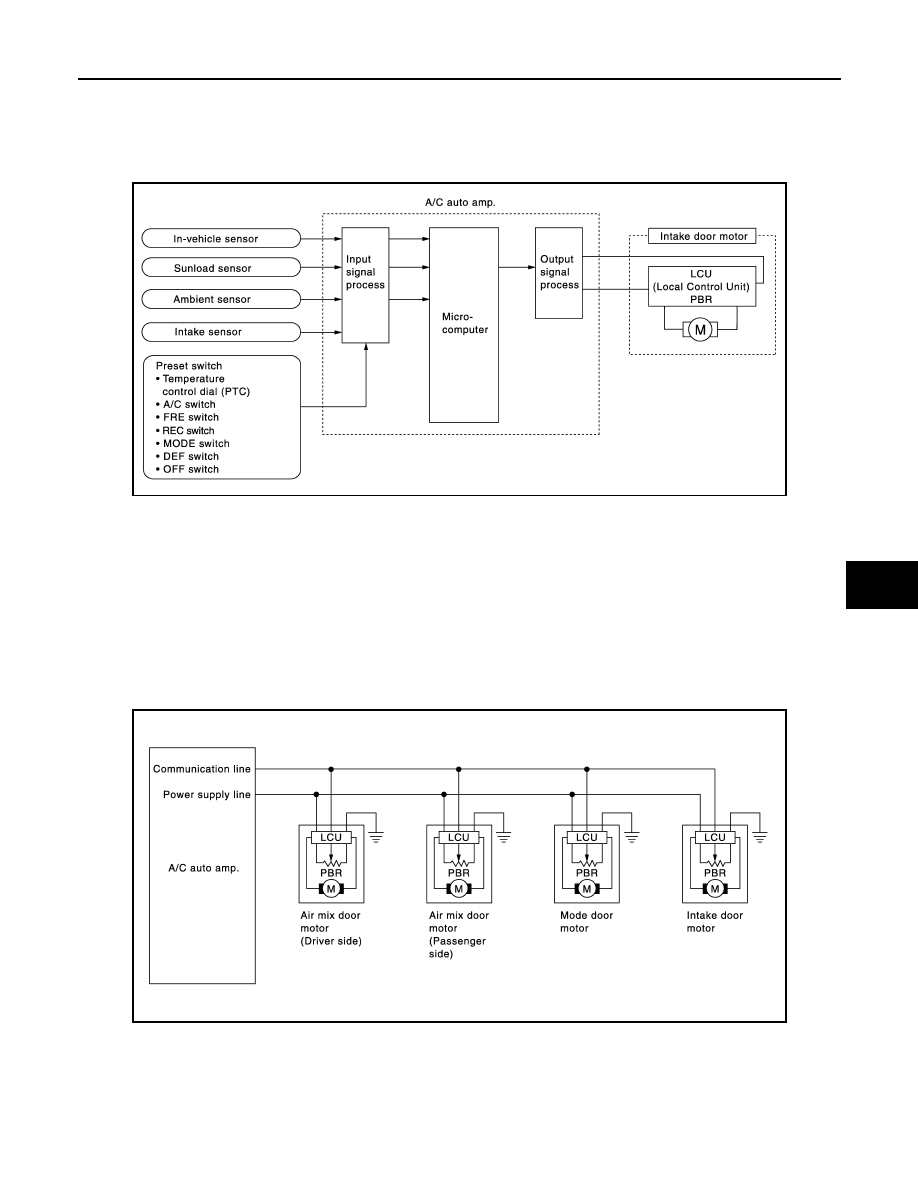
WITHOUT INTELLIGENT AIR CONDITIONER SYSTEM : System Diagram

INFOID:0000000003884722

WITHOUT INTELLIGENT AIR CONDITIONER SYSTEM : System Description

INFOID:0000000003884724

The intake door is automatically controlled by the temperature setting, ambient temperature, in-vehicle tem-
perature, intake temperature, amount of sunload and ON/OFF operation of the compressor.

SYSTEM OPERATION

The intake door control judges intake door position based on the ambient temperature, the intake air tempera-
ture and the in-vehicle temperature. When the DEF or OFF switches are pressed, the A/C auto amp. sets the
intake door to the FRE position.

Door Motor Circuit

Intake Door Control Specification

JPIIA1023GB

JSIIA1133GB

HAC-150

< FUNCTION DIAGNOSIS >

[WITH 7 INCH DISPLAY]

INTAKE DOOR CONTROL SYSTEM

• Intake door position is basically set to the FRE when the FRE indi-

cator is ON or DEF switch is ON.

• Intake door position is basically set to the REC when the REC indi-

cator is ON.

• The intake door automatic control selects the FRE, the 20% FRE,

or the REC depending on the target air mix door opening angle,
based on in-vehicle temperature, ambient temperature, and sun-
load.

WITH INTELLIGENT AIR CONDITIONER SYSTEM

WITH INTELLIGENT AIR CONDITIONER SYSTEM : System Diagram

INFOID:0000000003884723

WITH INTELLIGENT AIR CONDITIONER SYSTEM : System Description

INFOID:0000000003884725

The intake door is automatically controlled by the ambient atmospheric CO and NO

2, 

temperature setting,

ambient temperature, in-vehicle temperature, intake temperature, amount of sunload and ON/OFF operation
of the compressor.

SYSTEM OPERATION

The intake door control judges intake door position based on the ambient atmospheric CO and NO

2, 

ambient

temperature, the intake air temperature and the in-vehicle temperature. When DEF or OFF switches are
pressed, the A/C auto amp. sets the intake door at the FRE position.

JPIIA0634GB

JPIIA1024GB

INTAKE DOOR CONTROL SYSTEM

HAC-151

< FUNCTION DIAGNOSIS >

[WITH 7 INCH DISPLAY]

C

D

E

F

G

H

J

K

L

M

A

B

HAC

N

O

P

Door Motor Circuit

Intake Door Control Specification

• Intake door position is basically set to the FRE when the intake

indicator is OFF or DEF switch is ON.

• Intake door position is basically set to the REC when the intake

indicator is ON.

• The intake door automatic control selects the FRE, the 20% FRE,

or the REC depending on the target air mix door opening angle,
based on in-vehicle temperature, ambient temperature, and sun-
load.

Automatic Re-circulation Control System

In addition to the regular automatic control, intake door condition is
controlled by gas sensor output signal when auto recirculation mode
is selected. This system automatically controls the inlet to prevent a
smell of exhaust gas from getting into vehicle by receiving signals
from the gas sensor that detects ambient atmospheric CO and NO

2.

JSIIA1133GB

JPIIA0634GB

ZJIA1166E

HAC-152

< FUNCTION DIAGNOSIS >

[WITH 7 INCH DISPLAY]

BLOWER MOTOR CONTROL SYSTEM

BLOWER MOTOR CONTROL SYSTEM

System Diagram

INFOID:0000000003884727

System Description

INFOID:0000000003884728

Blower speed is automatically controlled by the temperature setting, ambient temperature, in-vehicle tempera-
ture, intake temperature, amount of sunload and air mix door position.
By pressing the AUTO switch, the blower motor starts to gradually increase air flow volume.
When engine coolant temperature is low, the blower motor operation is delayed to prevent cool air from flow-
ing.

SYSTEM OPERATION

System Operation

• For air flow, the manual selection (1-7) with the fan control dial has priority. 
• If the AUTO switch is pressed or if the DEF switch is pressed while in the OFF condition, it changes to the

automatic control by A/C auto amp. 

• When increasing the air flow, it changes the duty ratio of the blower motor drive signal to prevent the air flow

from suddenly increasing. 

• There are the following types of air flow control: starting air flow control, starting air flow control at low cool-

ant temperature, starting air flow control at high in-vehicle temperature, and air flow control at actuator oper-
ation in addition to manual control, normal automatic air flow control. 

Normal Automatic Air Flow Control

• When the target temperature is set by the temperature control dial of A/C control, the A/C auto amp. per-

forms the calculation and decides the target according to the signal from each sensor. 

• The A/C auto amp. changes the duty ratio of blower motor drive signal and controls the air flow continuously

so that the air flow becomes the target air flow. 

• The minimum air flow will change according to the sunload when the air discharge outlet is VENT or B/L. 

Fan Speed Control Specification

JPIIA0502GB

JPIIA0635GB


Content   ..  693  694  695  696   ..