Nissan Teana J32. Manual - part 675


  Index      Nissan     Nissan Teana J32 (2008 year) - Service and Repair Manual


Search            


Content   ..  673  674  675  676   ..


Nissan Teana J32. Manual - part 675


BLOWER MOTOR

HAC-69

< COMPONENT DIAGNOSIS >

[WITHOUT 7 INCH DISPLAY]

C

D

E

F

G

H

J

K

L

M

A

B

HAC

N

O

P

2.

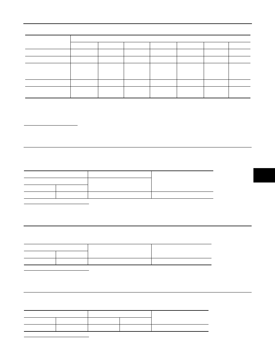
Check that the blower motor control signal changes according to each indicator signal. 

NOTE:
• Perform the inspection of each output device after starting the engine because the compressor is oper-

ated. 

• When choosing to “MODE 7”, error message is displayed but it is not malfunction.

Does it operate normally?

YES

>> INSPECTION END

NO

>> GO TO 3.

3.

CHECK POWER SUPPLY FOR BLOWER MOTOR

1.

Disconnect blower motor connector.

2.

Turn ignition switch ON.

3.

Check voltage between blower motor harness connector and ground.

Is the inspection result normal?

YES

>> GO TO 4.

NO

>> GO TO 7.

4.

CHECK BLOWER MOTOR GROUND CIRCUIT

1.

Turn ignition switch OFF.

2.

Check continuity between blower motor harness connector and ground.

Is the inspection result normal?

YES

>> GO TO 5.

NO

>> Repair harness or connector.

5.

CHECK BLOWER MOTOR CIRCUIT CONTINUITY

1.

Disconnect A/C auto amp. connector.

2.

Check continuity between blower motor harness connector and A/C auto amp. harness connector.

Is the inspection result normal?

Test item

MODE 1

MODE 2

MODE 3

MODE 4

MODE 5

MODE 6

MODE 7

Mode door position

VENT

B/L1

B/L2

AUTO FOOT

D/F

DEF

-

Intake door position

REC

REC

20% FRE

FRE

FRE

FRE

-

Air mix door position 
(driver & passenger 
side)

FULL COLD

FULL COLD

FULL HOT

FULL HOT

FULL HOT

FULL HOT

-

Blower motor duty ratio

37%

91%

65%

65%

65%

91%

-

Compressor (Magnet 
clutch)

ON

ON

OFF

OFF

ON

ON

-

(+)

(

)

Voltage

Blower motor

Connector

Terminal

M98

1

Ground

Battery voltage

Blower motor

Continuity

Connector

Terminal

M98

3

Ground

Existed

Blower motor

A/C auto amp.

Continuity

Connector

Terminal

Connector

Terminal

M98

2

M50

32

Existed

HAC-70

< COMPONENT DIAGNOSIS >

[WITHOUT 7 INCH DISPLAY]

BLOWER MOTOR

YES

>> GO TO 6.

NO

>> Repair harness or connector.

6.

CHECK A/C AUTO AMP. OUTPUT SIGNAL

1.

Reconnect blower motor connector and A/C auto amp. connector.

2.

Turn ignition switch ON.

3.

Set MODE switch to the VENT position.

4.

Check the output waveform between blower motor harness connector and ground using an oscilloscope,
while varying the fan speed from 1 to 7.

Is the inspection result normal?

YES

>> Replace the blower motor. 

NO

>> Replace the A/C auto amp. 

7.

CHECK POWER VOLTAGE OF BLOWER RELAY

1.

Turn the ignition switch OFF.

2.

Remove the blower relay. Refer to 

PG-101, "Fuse, Connector and Terminal Arrangement"

3.

Turn the ignition switch ON.

4.

Check the voltage between blower relay fuse block side terminal and ground. Refer to 

PG-101, "Fuse,

Connector and Terminal Arrangement"

 for relay terminal assignment. 

Is the inspection result normal?

YES

>> GO TO 8.

NO

>> Inspection the power supply circuit. Refer to 

PG-55, "Wiring Diagram - IGNITION POWER SUP-

PLY -"

.

8.

CHECK BLOWER RELAY

1.

Turn the ignition switch OFF.

2.

Install the blower relay. Refer to 

PG-101, "Fuse, Connector and Terminal Arrangement"

3.

Turn the ignition switch ON.

4.

Check the operating sound of blower relay. 

Is the inspection result normal?

YES

>> GO TO 9.

NO

>> Replace the blower relay. 

9.

CHECK FUSE

Check 15A fuses (Nos. 21 and 22). 

JPIIA1025GB

(+)

(

)

Voltage

Blower relay

1

Ground

Battery voltage

3

BLOWER MOTOR

HAC-71

< COMPONENT DIAGNOSIS >

[WITHOUT 7 INCH DISPLAY]

C

D

E

F

G

H

J

K

L

M

A

B

HAC

N

O

P

NOTE:
Refer to 

PG-101, "Fuse, Connector and Terminal Arrangement"

 for fuse location. 

Is the inspection result normal?

YES

>> Repair the harnesses or connectors.

NO

>> Replace the fuse after repairing the applicable circuit.

Component Inspection

INFOID:0000000003846362

1.

CHECK BLOWER MOTOR

1.

Remove the blower motor. Refer to 

VTL-32, "Exploded View"

2.

Check that the blower motor rotates smoothly. 

Is the inspection result normal?

YES

>> END.

NO

>> Replace blower motor.

HAC-72

< COMPONENT DIAGNOSIS >

[WITHOUT 7 INCH DISPLAY]

MAGNET CLUTCH

MAGNET CLUTCH

Description

INFOID:0000000003846363

The magnet clutch drives the compressor, by an IPDM E/R signal.

Component Function Check

INFOID:0000000003846364

1.

FUNCTION INSPECTION

1.

Press AUTO switch.

2.

“AUTO” is indicated on the display. 

3.

Check that the indicator of the A/C switch turns on. Check visually and by sound that the compressor is
operating (the discharge air temperature or fan speed varies depending on the ambient temperature, in-
vehicle temperature, and temperature setting). 

4.

Press the A/C switch. 

5.

Check that the indicator of the A/C switch turns OFF. Check visually and by sound that the compressor
stops. 

Does it operate normally?

YES

>> INSPECTION END

NO

>> Perform trouble diagnosis for the compressor. Refer to 

HAC-72, "Diagnosis Procedure"

Diagnosis Procedure

INFOID:0000000003846365

1.

INSPECTION IN AUTO ACTIVE TEST MODE

Perform “AUTO ACTIVE TEST”. Refer to 

PCS-11, "Diagnosis Description"

Does it operate normally?

YES

>> GO TO 5.

NO

>> GO TO 2.

2.

CHECK MAGNET CLUTCH

1.

Turn the ignition switch OFF.

2.

Disconnect the magnet clutch connector. 

3.

Directly apply the battery voltage to the magnet clutch. Check for operation visually and by sound. 

Does it operate normally?

YES

>> GO TO 3.

NO

>> Replace the compressor.

3.

CHECK MAGNET CLUTCH CIRCUIT CONTINUITY

1.

Turn the ignition switch OFF.

2.

Disconnect IPDM E/R connector.

3.

Check continuity between magnet clutch harness connector and IPDM E/R harness connector. 

Is the inspection result normal?

YES

>> GO TO 4.

NO

>> Repair harness or connector.

4.

CHECK FUSE

Check 10A fuse (No. 49). 
NOTE:
Refer to 

PG-101, "Fuse, Connector and Terminal Arrangement"

 for fuse location. 

Is the inspection result normal?

YES

>> Replace IPDM E/R.

NO

>> Replace the fuse after repairing the applicable circuit. 

IPDM E/R

Compressor

Continuity

Connector

Terminal

Connector

Terminal

F12

48

F18

1

Existed


Content   ..  673  674  675  676   ..