Nissan Teana J32. Manual - part 674


  Index      Nissan     Nissan Teana J32 (2008 year) - Service and Repair Manual


Search            


Content   ..  672  673  674  675   ..


Nissan Teana J32. Manual - part 674


POWER SUPPLY AND GROUND CIRCUIT

HAC-65

< COMPONENT DIAGNOSIS >

[WITHOUT 7 INCH DISPLAY]

C

D

E

F

G

H

J

K

L

M

A

B

HAC

N

O

P

POWER SUPPLY AND GROUND CIRCUIT

A/C AUTO AMP.

A/C AUTO AMP. : Diagnosis Procedure

INFOID:0000000003941309

1.

CHECK FUSE

Check 10A fuses [Nos. 3, 6 and 19, located in the fuse block (J/B)].
NOTE:
Refer to 

PG-101, "Fuse, Connector and Terminal Arrangement"

.

Is the inspection result normal?

YES

>> GO TO 2.

NO

>> Replace the fuse after repairing the applicable circuit. 

2.

CHECK A/C AUTO AMP. POWER SUPPLY CIRCUIT

1.

Disconnect the A/C auto amp. connector. 

2.

Check voltage between A/C auto amp. harness connector and ground. 

Is the inspection result normal?

YES

>> GO TO 3.

NO

>> Repair the harnesses or connectors.

3.

CHECK A/C AUTO AMP. CIRCUIT CONTINUITY

1.

Turn ignition switch OFF.

2.

Check continuity between A/C auto amp. harness connector and ground. 

Is the inspection result normal?

YES

>> INSPECTION END 

NO

>> Repair the harnesses or connectors.

A/C CONTROL

A/C CONTROL : Diagnosis Procedure

INFOID:0000000003846370

1.

CHECK A/C CONTROL POWER SUPPLY CIRCUIT

1.

Disconnect the A/C control connector. 

2.

Turn ignition switch ON.

3.

Check voltage between A/C control harness connector and ground. 
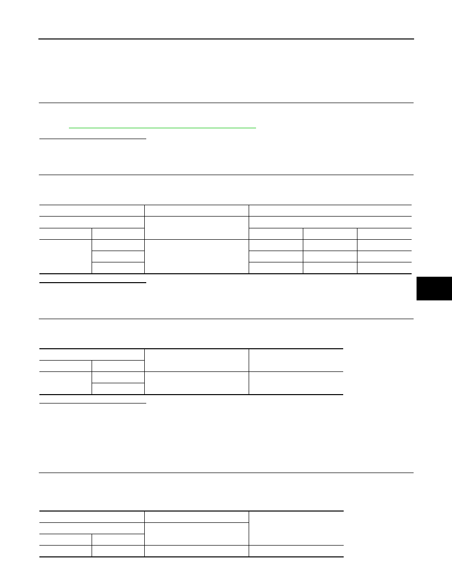
(+)

(

)

Voltage

A/C auto amp.

Ignition switch position

Connector

Terminal

OFF

ACC

ON

M50

17

Ground

Approx. 0 V

Battery voltage

Battery voltage

20

Approx. 0 V

Approx. 0 V

Battery voltage

40

Battery voltage

Battery voltage

Battery voltage

A/C auto amp.

Continuity

Connector

Terminal

M50

19

Ground

Existed

39

(+)

(

)

Voltage

A/C control

Connector

Terminal

M95

1

Ground

Battery voltage

HAC-66

< COMPONENT DIAGNOSIS >

[WITHOUT 7 INCH DISPLAY]

POWER SUPPLY AND GROUND CIRCUIT

Is the inspection result normal?

YES

>> GO TO 2.

NO

>>

Check 10A fuse (No. 3, located in the fuse block). Refer to 

PG-101, "Fuse, Connector and Ter-

minal Arrangement"

• If fuse is OK, check harness for open circuit. Repair or replace if necessary.
• If fuse is NG, replace fuse and check for short circuit. Repair or replace if necessary.

2.

CHECK A/C CONTROL CIRCUIT CONTINUITY

1.

Turn ignition switch OFF.

2.

Check continuity between A/C control harness connector and ground. 

Is the inspection result normal?

YES

>> Replace the A/C control. 

NO

>> Repair the harnesses or connectors.

A/C DISPLAY

A/C DISPLAY : Diagnosis Procedure

INFOID:0000000003846371

1.

CHECK A/C DISPLAY POWER SUPPLY CIRCUIT

1.

Disconnect the A/C display connector. 

2.

Turn ignition switch ON.

3.

Check voltage between A/C display harness connector and ground. 

Is the inspection result normal?

YES

>> GO TO 2.

NO

>> Repair the harnesses or connectors.

2.

CHECK A/C DISPLAY CIRCUIT CONTINUITY

1.

Turn ignition switch OFF.

2.

Check continuity between A/C display harness connector and ground. 

Is the inspection result normal?

YES

>> Replace the A/C display. 

NO

>>

Check 10A fuse (No. 3, located in the fuse block). Refer to 

PG-101, "Fuse, Connector and Ter-

minal Arrangement"

• If fuse is OK, check harness for open circuit. Repair or replace if necessary.
• If fuse is NG, replace fuse and check for short circuit. Repair or replace if necessary.

A/C control

Continuity

Connector

Terminal

M95

2

Ground

Existed

(+)

(

)

Voltage

A/C display

Connector

Terminal

M16

6

Ground

Battery voltage

A/C display

Continuity

Connector

Terminal

M16

1

Ground

Existed

A/C AUTO AMP.

HAC-67

< COMPONENT DIAGNOSIS >

[WITHOUT 7 INCH DISPLAY]

C

D

E

F

G

H

J

K

L

M

A

B

HAC

N

O

P

A/C AUTO AMP.

Description

INFOID:0000000003940951

COMPONENT DESCRIPTION

A/C Auto Amp. (Air Conditioner Automatic Amplifier)

The A/C auto amp. (1) has a built-in microcomputer that processes
information sent from various sensors needed for air conditioner
operation. The air mix door motors, the mode door motor, the intake
door motor, the blower motor and the compressor are then con-
trolled.
When the various switches and temperature control dial are oper-
ated, data is input to the A/C auto amp. from the A/C control.

Component Function Check

INFOID:0000000003940952

1.

CHECK OPERATION

1.

Press the AUTO switch, and then check that “AUTO” is shown on the display. 

2.

Operate the temperature control dial (driver side). Check that the fan speed or outlet changes. (The dis-
charge air temperature or fan speed varies depending on the ambient temperature, in-vehicle tempera-
ture, and temperature setting.) 

Does it operate normally?

YES

>> INSPECTION END

NO

>> Perform trouble diagnosis for the A/C system. Refer to 

HAC-67, "Diagnosis Procedure"

.

Diagnosis Procedure

INFOID:0000000003940953

1.

INSPECTION BY FAIL-SAFE FUNCTION

1.

Turn the ignition switch ON.

2.

After approximately 30 seconds, check that the air conditioner is operated by the fail-safe function (the
operation display of air conditioner is not performed). Refer to 

HAC-84, "Fail-Safe"

Is the fail-safe function operated? 

YES

>> GO TO 3.

NO

>> GO TO 2.

2.

CHECK A/C AUTO AMP. POWER SUPPLY CIRCUIT AND GROUND

Check A/C auto amp. power supply circuit and ground circuit. Refer to 

HAC-65, "A/C AUTO AMP. : Diagnosis

Procedure"

.

Is the inspection result normal?

YES

>> GO TO 3.

NO

>> Repair or replace parts according to the inspection results.

3.

CHECK A/C CONTROL SIGNAL CIRCUIT

Check the A/C control signal circuit. Refer to 

HAC-74, "Diagnosis Procedure"

.

Is the inspection result normal?

YES

>> INSPECTION END

NO

>> Repair or replace parts according to the inspection results.

JPIIA0894ZZ

HAC-68

< COMPONENT DIAGNOSIS >

[WITHOUT 7 INCH DISPLAY]

BLOWER MOTOR

BLOWER MOTOR

Description

INFOID:0000000003846359

COMPONENT DESCRIPTION

Brush-less Motor

The blower motor utilizes a brush-less motor with a rotating magnet.
Quietness is improved over previous motors where the brush was
the point of contact and the coil rotated.

Blower Motor Circuit

Component Function Check

INFOID:0000000003846360

1.

CHECK OPERATION

1.

Warm up the engine.

2.

Operate the fan control dial. Check that the fan speed and indicator are switched for all fan speeds. 

Does it operate normally?

YES

>> INSPECTION END

NO

>> Perform trouble diagnosis for the blower motor. Refer to 

HAC-68, "Diagnosis Procedure"

.

Diagnosis Procedure

INFOID:0000000003846361

1.

CHECK WITH SELF-DIAGNOSIS FUNCTION OF CONSULT-III

1.

Using CONSULT-III, perform “SELF-DIAGNOSIS RESULTS” of HVAC. 

2.

Check if any DTC is displayed in the self-diagnosis results. 

NOTE:
If DTC is displayed along with DTC U1000 or U1010, first diagnose the DTC U1000 or U1010. Refer to 

HAC-

42, "DTC Logic"

 or 

HAC-43, "DTC Logic"

Is any DTC displayed?

YES

>> Perform the diagnosis that is applicable to the sensor and actuator. Refer to 

HAC-85, "DTC

Index"

NO

>> GO TO 2.

2.

CHECK WITH ACTIVE TEST OF CONSULT-III

1.

Using CONSULT-III, perform “HVAC TEST” “ACTIVE TEST” of HVAC to check each output device. Refer
to 

HAC-38, "CONSULT-III Function"

.

NOTE:
Perform the ACTIVE TEST after starting the engine because the compressor is operated. 

ZHA152H

JSIIA0999ZZ


Content   ..  672  673  674  675   ..