Nissan Teana J32. Manual - part 656
HA-52
< ON-VEHICLE REPAIR >
EVAPORATOR
EVAPORATOR
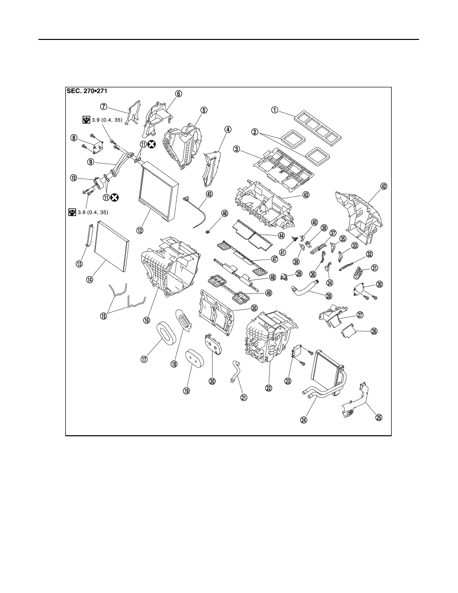
Exploded View
INFOID:0000000003825218
1.
Ventilator seal
2.
Defroster seal
3.
Distributor upper case
4.
Center case
5.
Heater & cooling unit case cover
6.
Foot duct 1 (right)
7.
Foot duct 2 (right)
8.
Air mix door motor (passenger side)
9.
Evaporator pipe assembly
10. Expansion valve
11.
O-ring
12.
Evaporator
13. Filter cover
14.
Air conditioner filter
15.
Case packing
16. Heater & cooling unit case (right)
17.
Cooler pipe grommet
18.
Grommet
19. Heater pipe grommet
20.
Heater pipe support
21.
Drain hose
22. Heater & cooling unit case (left)
23.
Air mix door motor (driver side)
24.
Heater core
25. Heater pipe cover
26.
Foot duct 2 (left)
27.
Foot duct 1 (left)
28. Aspirator hose
29.
Aspirator
30.
Mode door motor
31. Main link
32.
Rod link
33.
Ventilator door link
34. Mode door lever
35.
Ventilator door lever
36.
Max. cool door link
JPIIA0906GB