Nissan Teana J32. Manual - part 654
HA-44
< ON-VEHICLE REPAIR >
HIGH-PRESSURE PIPE
HIGH-PRESSURE PIPE
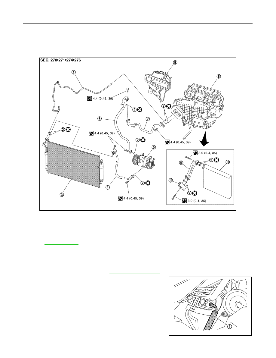
Exploded View
INFOID:0000000003839912
HA-14, "Refrigerant Connection"
.
Removal and Installation
INFOID:0000000003839913
REMOVAL
1.
Remove low-pressure pipe. Refer to
2.
Disconnect high-pressure pipe (1) from expansion valve.
CAUTION:
Cap or wrap the joint of the A/C piping and expansion valve
with suitable material such as vinyl tape to avoid the entry
of air.
1.
High-pressure pipe
2.
O-ring
3.
Condenser
4.
High-pressure flexible hose
5.
Compressor
6.
Low-pressure flexible hose
7.
Low-pressure pipe
8.
Heater & cooling unit assembly
9.
Blower unit
10. Evaporator pipe assembly
11.
Expansion valve
12. Evaporator
Refer to
for symbols in the figure.
JPIIA0952GB
JPIIA0972ZZ