Nissan Teana J32. Manual - part 647


  Index      Nissan     Nissan Teana J32 (2008 year) - Service and Repair Manual


Search            


Content   ..  645  646  647  648   ..


Nissan Teana J32. Manual - part 647


HA-16

< PRECAUTION >

PRECAUTIONS

• Perform leakage test and make sure that there is no leakage from connections after connecting line.

Disconnect that line and replace the O-ring when the refrigerant leaking point is found. Then tighten
connections of seal seat to the specified torque.

Service Equipment

INFOID:0000000003795889

RECOVERY/RECYCLING EQUIPMENT

Be certain to follow the manufacturer’s instructions for machine operation and machine maintenance. Never
introduce any refrigerant other than that specified into the machine.

ELECTRICAL LEAK DETECTOR

Be certain to follow the manufacturer’s instructions for tester operation and tester maintenance.
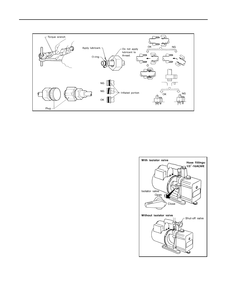
VACUUM PUMP

The lubricant contained inside the vacuum pump is not compatible
with the specified lubricant for HFC-134a (R-134a) A/C systems.
The vent side of the vacuum pump is exposed to atmospheric pres-
sure. So the vacuum pump lubricant may migrate out of the pump
into the service hose. This is possible when the pump is switched
OFF after evacuation (vacuuming) and hose is connected to it.
To prevent this migration, use a manual valve placed near the hose-
to-pump connection, as per the following.
• Vacuum pumps usually have a manual isolator valve as part of the

pump. Close this valve to isolate the service hose from the pump.

• Use a hose equipped with a manual shut-off valve near the pump

end for pumps without an isolator. Close the valve to isolate the
hose from the pump.

• Disconnect the hose from the pump if the hose has an automatic

shut-off valve. As long as the hose is connected, the valve is open
and lubricating oil may migrate.

Some one-way valves open when vacuum is applied and close
under no vacuum condition. Such valves may restrict the pump’s
ability to pull a deep vacuum and are not recommended.

MANIFOLD GAUGE SET

RHA861F

RHA270DA

PRECAUTIONS

HA-17

< PRECAUTION >

C

D

E

F

G

H

J

K

L

M

A

B

HA

N

O

P

Be certain that the gauge face indicates HFC-134a or R-134a. Be
sure the gauge set has 1/2

-16 ACME threaded connections for ser-

vice hoses. Confirm the set has been used only with refrigerant
HFC-134a (R-134a) and specified lubricants.

SERVICE HOSES

Be certain that the service hoses display the markings described
(colored hose with black stripe). All hoses must equip positive shut-
off devices (either manual or automatic) near the end of the hoses
opposite to the manifold gauge.

SERVICE COUPLERS

Never attempt to connect HFC-134a (R-134a) service couplers to a
CFC-12 (R-12) A/C system. The HFC-134a (R-134a) couplers do
not properly connect to the CFC-12 (R-12) system. However, if an
improper connection is attempted, discharging and contamination
may occur.

REFRIGERANT WEIGHT SCALE

Verify that no refrigerant other than HFC-134a (R-134a) and speci-
fied lubricants have been used with the scale. The hose fitting must
be 1/2

-16 ACME if the scale controls refrigerant flow electronically.

CALIBRATING ACR4 WEIGHT SCALE

Calibrate the scale each three month.
To calibrate the weight scale on the ACR4:

1.

Press “Shift/Reset” and “Enter” at the same time.

2.

Press “8787”“A1” is displayed.

3.

Remove all weight from the scale.

4.

Press “0”, then press “Enter”“0.00” is displayed and change to “A2”.

SHA533D

RHA272D

Shut-off valve rotation

A/C service valve

Clockwise

Open

Counterclockwise

Close

RHA273D

RHA274D

HA-18

< PRECAUTION >

PRECAUTIONS

5.

Place a known weight (dumbbell or similar weight), between 4.5 and 8.6 kg (10 and 19 lb.) on the center
of the weight scale.

6.

Enter the known weight using four digits. (Example 10 lb. = 10.00, 10.5 lb. = 10.50)

7.

Press “Enter”— the display returns to the vacuum mode.

8.

Press “Shift/Reset” and “Enter” at the same time.

9.

Press “6”— the known weight on the scale is displayed.

10. Remove the known weight from the scale. “0.00” is displayed.

11. Press “Shift/Reset” to return the ACR4 to the program mode.

CHARGING CYLINDER

Using a charging cylinder is not recommended. Refrigerant may be vented into air from cylinder’s top valve
when filling the cylinder with refrigerant. Also, the accuracy of the cylinder is generally less than that of an
electronic scale or of quality recycle/recharge equipment.

COMPRESSOR

HA-19

< PRECAUTION >

C

D

E

F

G

H

J

K

L

M

A

B

HA

N

O

P

COMPRESSOR

General Precautions

INFOID:0000000003795891

CAUTION:

• Plug all openings to prevent moisture and foreign matter from entering.
• Store it in the same way at it is when mounted on the car when the compressor is removed.
• Follow “Maintenance of Lubricant Quantity in Compressor” exactly when replacing or repairing

compressor. Refer to 

HA-28, "Maintenance of Lubricant Quantity"

.

• Keep friction surfaces between clutch and pulley clean. Wipe it off by using a clean waste cloth

moistened with thinner if the surface is contaminated with lubricant.

• Turn the compressor shaft by hand more than five turns in both directions after compressor service

operation. This distributes equally lubricant inside the compressor. Let the engine idle and operate
the compressor for one hour after the compressor is installed.

• Apply voltage to the new one and check for normal operation after replacing the compressor magnet

clutch.


Content   ..  645  646  647  648   ..