Nissan Teana J32. Manual - part 592


  Index      Nissan     Nissan Teana J32 (2008 year) - Service and Repair Manual


Search            


Content   ..  590  591  592  593   ..


Nissan Teana J32. Manual - part 592


EXL-338

< ON-VEHICLE MAINTENANCE >

[HALOGEN TYPE]

HEADLAMP AIMING ADJUSTMENT

Low beam distribution on the screen

Unit: mm (in)

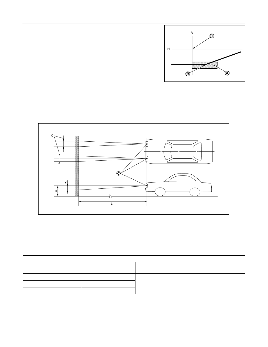
Aiming Adjustment Procedure (High Beam)

INFOID:0000000003829237

1.

Place the screen. 
NOTE:
• Stop the vehicle at the perpendicular angle to the wall. 
• Set the screen so that it is perpendicular to a level load surface. 

JSLIA0030ZZ

A.

Aiming adjustment area

B.

Elbow point

C.

Headlamp center

H.

Horizontal center line of headlamp

V.

Vertical center line of headlamp

C.

Vertical center line of headlamp H.

Horizontal center line of headlamp

L.

Distance from headlamp center to screen

X.

Aiming adjustment area
(lateral)

Y.

Aiming adjustment area
(Vertical)

Distance from headlamp center to screen (L)

: 10m (32.8 ft)

Aiming adjustment area

Vertical direction (Y)

(Lower side from headlamp center height)

Lateral direction (X)

(Right and left side from headlamp centerline)

Highest light axis

100 (3.94)

0-100 (3.94)

Target light axis

120 (4.72)

Lowest light axis

150 (5.91)

JPLIA1062ZZ

HEADLAMP AIMING ADJUSTMENT

EXL-339

< ON-VEHICLE MAINTENANCE >

[HALOGEN TYPE]

C

D

E

F

G

H

I

J

K

M

A

B

EXL

N

O

P

2.

Face the vehicle squarely toward the screen and make the distance between the headlamp center and
the screen 10 m (32.8 ft).

3.

Start the engine and illuminate the headlamp (HI). 
NOTE:
Block light from the headlamp that is not being adjusted with a thick fabric or another object, so that it
does not reach the adjustment screen. 

CAUTION:

Do not cover lens surface with tape, etc. because it is made from plastic.

4.

Use the aiming adjustment screw to adjust the elbow point projected by the low beams on the screen, so
that it is within the aiming adjustment area. 

High beam distribution on the screen

JSLIA0030ZZ

A.

Aiming adjustment area

B.

Elbow point

C.

Headlamp center

H.

Horizontal center line of headlamp

V.

Vertical center line of headlamp

C.

Vertical center line of headlamp H.

Horizontal center line of headlamp

L.

Distance from headlamp center to screen

X.

Aiming adjustment area
(lateral)

Y.

Aiming adjustment area
(Vertical)

Distance from headlamp center to screen (L)

: 10m (32.8 ft)

JPLIA1062ZZ

EXL-340

< ON-VEHICLE MAINTENANCE >

[HALOGEN TYPE]

HEADLAMP AIMING ADJUSTMENT

Unit: mm (in)

Aiming adjustment area

Vertical direction (Y)

(Lower side from headlamp center height)

Lateral direction (X)

(Right and left side from headlamp centerline)

Highest light axis

106 (4.17)

0-100 (3.94)

Target light axis

120 (4.72)

Lowest light axis

164 (6.46)

FRONT FOG LAMP AIMING ADJUSTMENT

EXL-341

< ON-VEHICLE MAINTENANCE >

[HALOGEN TYPE]

C

D

E

F

G

H

I

J

K

M

A

B

EXL

N

O

P

FRONT FOG LAMP AIMING ADJUSTMENT

Description

INFOID:0000000003894358

PREPARATION BEFORE ADJUSTING

NOTE:
• For details, refer to the regulations in your own country.

Before performing aiming adjustment, check the following. 

• Adjust the tire pressure to the specification.
• Fill with fuel, engine coolant and each oil.
• Maintain the unloaded vehicle condition. (Remove luggage from the passenger compartment and the lug-

gage room.)
NOTE:
Do not remove the temporary tire, jack and on-vehicle tool. 

• Wipe out dirt on the headlamp.

CAUTION:

Never use organic solvent (thinner, gasoline etc.)

• Ride alone on the driver seat.

AIMING ADJUSTMENT SCREW

• Turn the aiming adjusting screw for adjustment.

• For the position and direction of the adjusting screw, refer to the

figure.
NOTE:
A screwdriver or hexagonal wrench [6 mm (0.24 in)] can be used
for adjustment.

Aiming Adjustment Procedure

INFOID:0000000003894359

1.

Place the screen.
NOTE:
• Stop the vehicle facing the wall.
• Place the board on a plain road vertically.

2.

Face the vehicle with the screen. Maintain 10 m (32.8 ft) between the front fog lamp center and the
screen.

3.

Start the engine. Illuminate the front fog lamp.

CAUTION:

Never cover the lens surface with a tape etc. The lens is made of resin.
NOTE:
Shut off the headlamp light with the board to prevent from illuminating the adjustment screen.

4.

Adjust the cutoff line height (A) with the aiming adjustment screw so that the distance (X) between the hor-
izontal center line of front fog lamp (H) and (A) becomes 200 mm (7.87 in).

Front fog lamp light distribution on the screen 

A: UP

B: DOWN

JPLIA1086ZZ

JPLIA0008ZZ


Content   ..  590  591  592  593   ..