Nissan Teana J32. Manual - part 489
EM-80
< DISASSEMBLY AND ASSEMBLY >
REAR TIMING CHAIN CASE
Disassembly and Assembly
INFOID:0000000003802282
DISASSEMBLY
1.
Remove front timing chain case and timing chain. Refer to
.
2.
Remove water pump. Refer to
.
3.
Remove oil pans (upper and lower) and oil strainer. Refer to
.
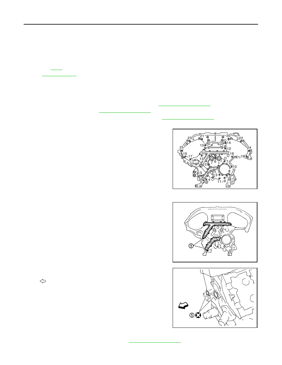
4.
Remove rear timing chain case as follows:
a.
Loosen and remove mounting bolts in reverse order as shown in
the figure.
b.
Cut liquid gasket using the seal cutter [SST: KV10111100
(J37228)] and remove rear timing chain case.
CAUTION:
• Never remove plate metal cover (1) of oil passage.
• After removal, handle rear timing chain case carefully so
it does not tilt, cant, or warp under a load.
5.
Remove O-rings (1) from cylinder block.
6.
Remove timing chain tensioners (secondary) from cylinder head as follows, if necessary.
a.
Remove camshaft brackets (No. 1). Refer to
19. Valve timing control cover (bank 1)
20.
Intake valve timing control sole-
noid valve (bank 1)
21.
Seal ring
22. Water pump cover
23. Front oil seal
24.
Crankshaft pulley
25. Crankshaft pulley bolt
26.
Intake valve timing control sole-
noid valve (bank 2)
27.
Valve timing control cover (bank 2)
28.
Valve timing control cover gasket
(bank 2)
A.
for symbols in the figure.
JPBIA1641ZZ
JPBIA0088ZZ
: Engine front
JPBIA0090ZZ