Nissan Teana J32. Manual - part 480
EM-44
< ON-VEHICLE REPAIR >
FUEL INJECTOR AND FUEL TUBE
FUEL INJECTOR AND FUEL TUBE
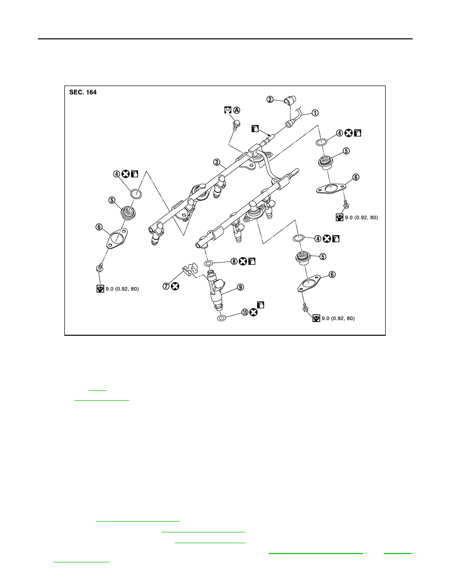
Exploded View
INFOID:0000000003802264
CAUTION:
Never remove or disassemble parts unless instructed as shown in the figure.
Removal and Installation
INFOID:0000000003802265
REMOVAL
WARNING:
• Put a “CAUTION: FLAMMABLE” sign in the workshop.
• Be sure to work in a well ventilated area and furnish workshop with a CO
2
fire extinguisher.
• Never smoke while servicing fuel system. Keep open flames and sparks away from the work area.
• To avoid the danger of being scalded, never drain engine coolant when engine is hot.
1.
Remove air duct (inlet), air cleaner cases (upper and lower) with mass air flow sensor and air duct assem-
bly. Refer to
.
2.
Remove engine cover. Refer to
3.
Release the fuel pressure. Refer to
.
4.
Remove front wiper arm and extension cowl top. Refer to
1.
Fuel feed hose
2.
Quick connector cap
3.
Fuel tube
4.
O-ring
5.
Fuel damper
6.
Fuel damper cap
7.
Clip
8.
O-ring (black)
9.
Fuel injector
10. O-ring (green)
A.
Refer to
Refer to
for symbols in the figure.
JPBIA1714GB