Nissan Teana J32. Manual - part 477
EM-32
< ON-VEHICLE REPAIR >
INTAKE MANIFOLD
INTAKE MANIFOLD
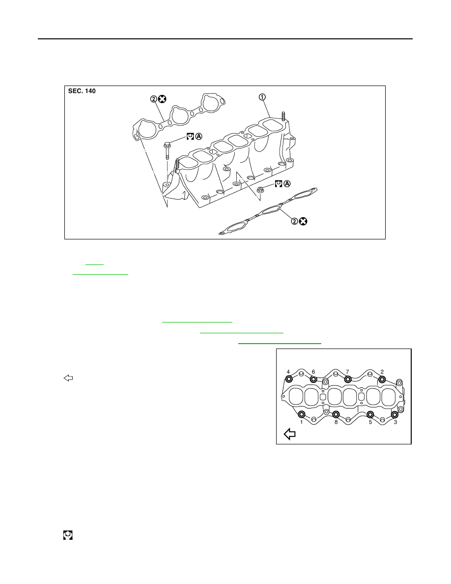
Exploded View
INFOID:0000000003802255
Removal and Installation
INFOID:0000000003802256
REMOVAL
1.
Release fuel pressure. Refer to
.
2.
Remove intake manifold collector. Refer to
3.
Remove fuel tube and fuel injector assembly. Refer to
.
4.
Loosen mounting nuts and bolts in reverse order as shown in
the figure to remove intake manifold with power tool.
5.
Remove gaskets.
CAUTION:
Cover engine openings to avoid entry of foreign materials.
INSTALLATION
Note the following, and install in the reverse order or removal.
Intake Manifold
• If stud bolts were removed, install them and tighten to the specified torque below.
1.
Intake manifold
2.
Gasket
A.
Refer to
Refer to
for symbols in the figure.
JPBIA1629GB
: Engine front
JPBIA1630ZZ
: 10.8 N·m (1.1 kg-m, 8 ft-lb)