Nissan Teana J32. Manual - part 475
EM-24
< ON-VEHICLE REPAIR >
ENGINE COVER
ON-VEHICLE REPAIR
ENGINE COVER
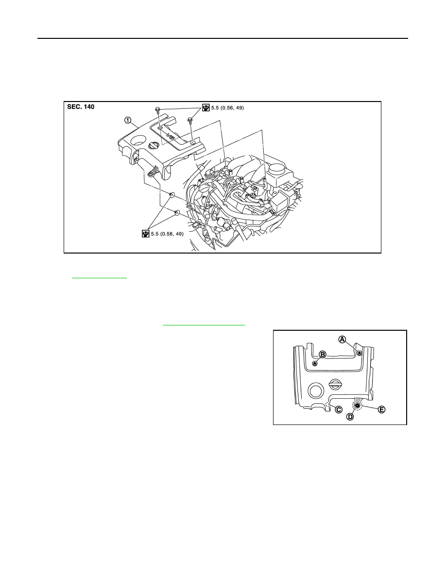
Exploded View
INFOID:0000000003802246
Removal and Installation
INFOID:0000000003802247
REMOVAL
1.
Remove air duct (inlet). Refer to
2.
Remove engine cover mounting bolts (A), (B).
3.
Draw and pull out engine cover from engine cover mounting bolts (C), (D).
CAUTION:
• Pull engine cover from mounting bolt (D) holding with hand the position (E) as shown in the fig-
ure.
• Never damage or scratch engine cover when installing or removing.
4.
Remove engine mounting bolts (C), (D), if necessary.
INSTALLATION
Install in the reverse order of removal.
1.
Engine cover
Refer to
for symbols in the figure.
JPBIA1712GB
JPBIA1718ZZ