Nissan Teana J32. Manual - part 387
EC-86
< FUNCTION DIAGNOSIS >
[VQ25DE, VQ35DE]
INTAKE VALVE TIMING CONTROL
INTAKE VALVE TIMING CONTROL
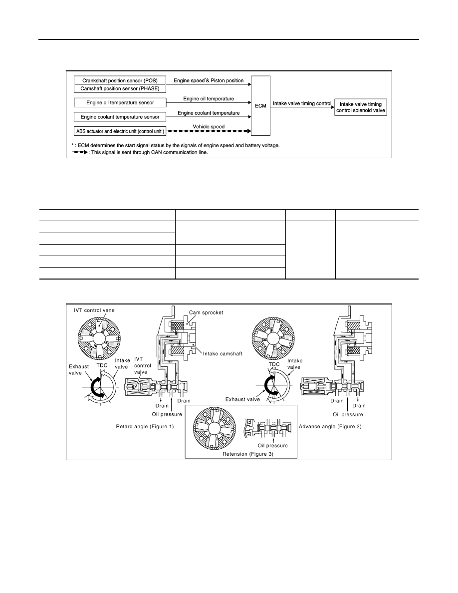
System Diagram
INFOID:0000000003856494
System Description
INFOID:0000000003856495
INPUT/OUTPUT SIGNAL CHART
*: This signal is sent to the ECM through CAN communication line
SYSTEM DESCRIPTION
This mechanism hydraulically controls cam phases continuously with the fixed operating angle of the intake
valve.
The ECM receives signals such as crankshaft position, camshaft position, engine speed, and engine coolant
temperature. Then, the ECM sends ON/OFF pulse duty signals to the intake valve timing (IVT) control sole-
noid valve depending on driving status. This makes it possible to control the shut/open timing of the intake
valve to increase engine torque in low/mid speed range and output in high-speed range.
JMBIA1491GB
Sensor
Input signal to ECM
ECM function
Actuator
Crankshaft position sensor (POS)
Engine speed and piston position
Intake valve
timing control
Intake valve timing control
solenoid valve
Camshaft position sensor (PHASE)
Engine oil temperature sensor
Engine oil temperature
Engine coolant temperature sensor
Engine coolant temperature
ABS actuator and electric unit (control unit)
Vehicle speed*
JMBIA0060GB