Nissan Teana J32. Manual - part 235
REAR DISC BRAKE
BR-43
< ON-VEHICLE REPAIR >
C
D
E
G
H
I
J
K
L
M
A
B
BR
N
O
P
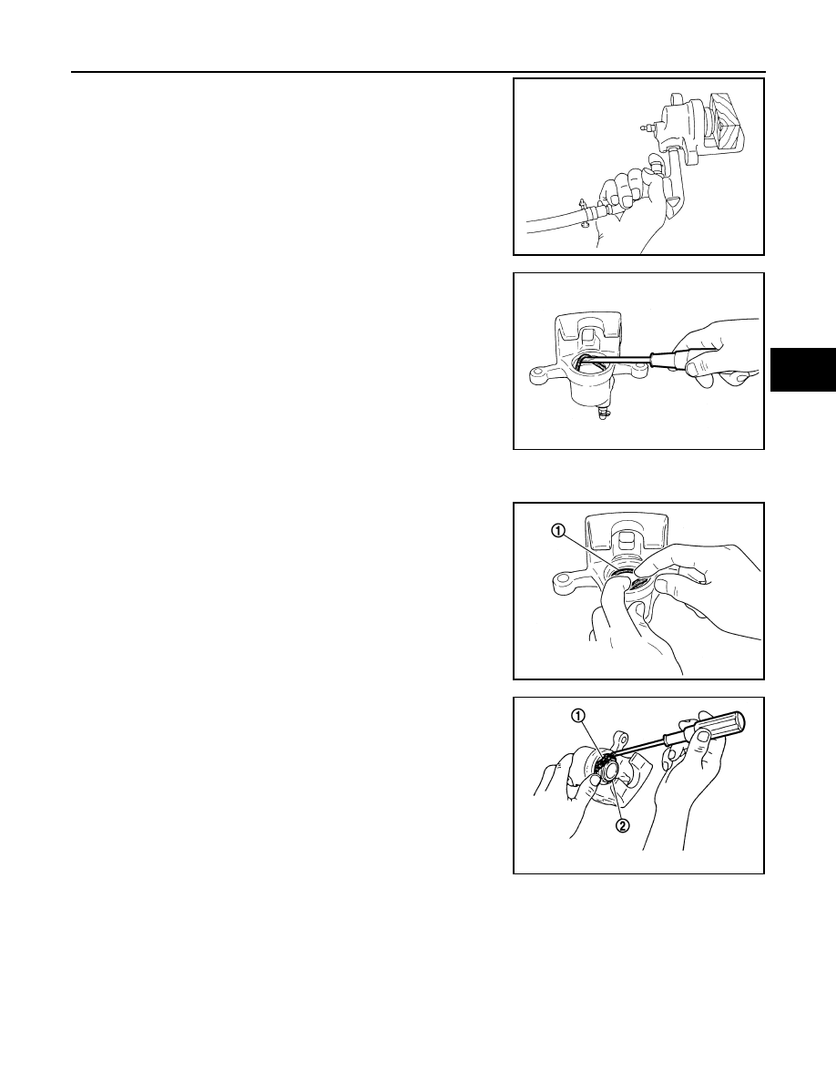
5.
Place a wooden block as shown in the figure, and blow air from
union bolt mounting hole to remove piston and piston boot.
CAUTION:
Never get fingers caught in the piston.
6.
Remove piston seal from cylinder body using suitable tool.
CAUTION:
Be careful not to damage a cylinder inner wall.
7.
Remove bleeder valve and cap.
ASSEMBLY
1.
Install bleeder valve and cap.
2.
Apply rubber grease to piston seal (1), and install to cylinder
body.
CAUTION:
Never reuse piston seal.
3.
Apply rubber grease to piston boot (1). Cover the piston (2) end
with the piston boot, and then install cylinder side lip on the pis-
ton boot securely into the groove on cylinder body.
CAUTION:
Never reuse piston boot.
BRD0041D
JPFIA0038ZZ
JPFIA0039ZZ
JPFIA0040ZZ