Nissan Teana J32. Manual - part 234
REAR DISC BRAKE
BR-39
< ON-VEHICLE REPAIR >
C
D
E
G
H
I
J
K
L
M
A
B
BR
N
O
P
REAR DISC BRAKE
BRAKE PAD
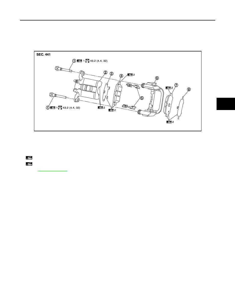
BRAKE PAD : Exploded View
INFOID:0000000003811211
BRAKE PAD : Removal and Installation
INFOID:0000000003811212
REMOVAL
WARNING:
Clean any dust from the brake caliper and brake pads with a vacuum dust collector. Never blow with
compressed air.
CAUTION:
• Never depress the brake pedal while removing the brake pads or the cylinder body because the pis-
ton may pop out.
• Never spill or splash brake fluid on the disc rotor.
1.
Remove tires.
2.
Remove the upper sliding pin bolt.
3.
Suspend the cylinder body with suitable wire so that the brake hose will not stretch. Remove the brake
pads and shims from the torque member.
CAUTION:
• Never deform the pad retainers if removing the pad retainers.
• Never damage the piston boot.
• Never drop the brake pad and shims.
INSTALLATION
WARNING:
Clean any dust from the brake caliper and brake pads with a vacuum dust collector. Never blow with
compressed air.
CAUTION:
1.
Sliding pin bolt
2.
Cylinder body
3.
Inner shim
4.
Inner pad (only RH side with pad
wear sensor)
5.
Pad retainer
6.
Torque member
7.
Outer pad
8.
Outer shim
1: Apply rubber grease.
2: Apply PBC (Poly Butyl Cuprysil) grease or silicone-based grease.
Refer to
for symbols not described on the above.
JPFIA0354GB