Nissan Teana J32. Manual - part 190
AV
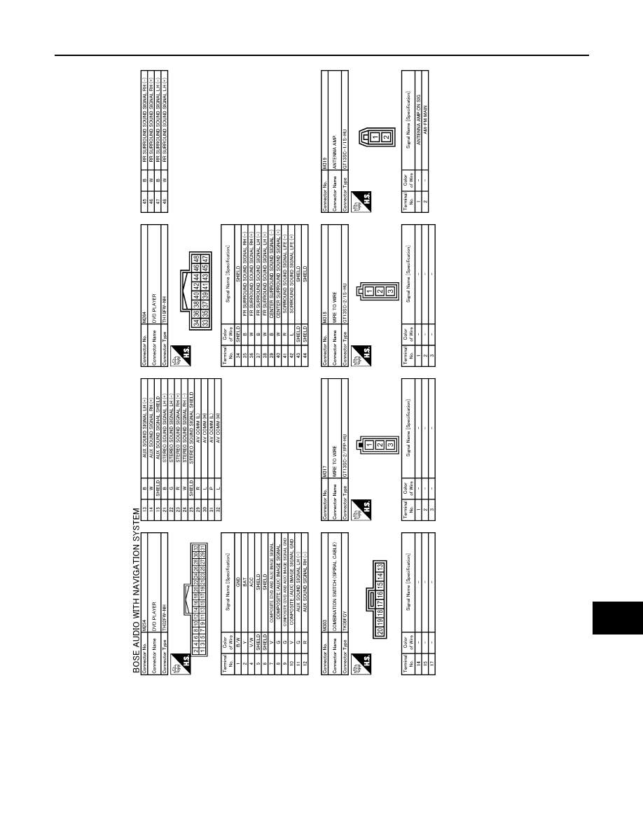
DVD PLAYER
AV-615
< ECU DIAGNOSIS >
[BOSE AUDIO WITH NAVIGATION]
C
D
E
F
G
H
I
J
K
L
M
B
A
O
P
JCNWM0915GB
|
|
|
AV DVD PLAYER AV-615 < ECU DIAGNOSIS > [BOSE AUDIO WITH NAVIGATION] C D E F G H I J K L M B A O P JCNWM0915GB |