Nissan Teana J32. Manual - part 161
 

  Index      Nissan     Nissan Teana J32 (2008 year) - Service and Repair Manual


Search            


Content   ..  159  160  161  162   ..


Nissan Teana J32. Manual - part 161


AV

AV CONTROL UNIT

AV-499

< ECU DIAGNOSIS >

[BOSE AUDIO WITH NAVIGATION]

C

D

E

F

G

H

I

J

K

L

M

B

A

O

P

66

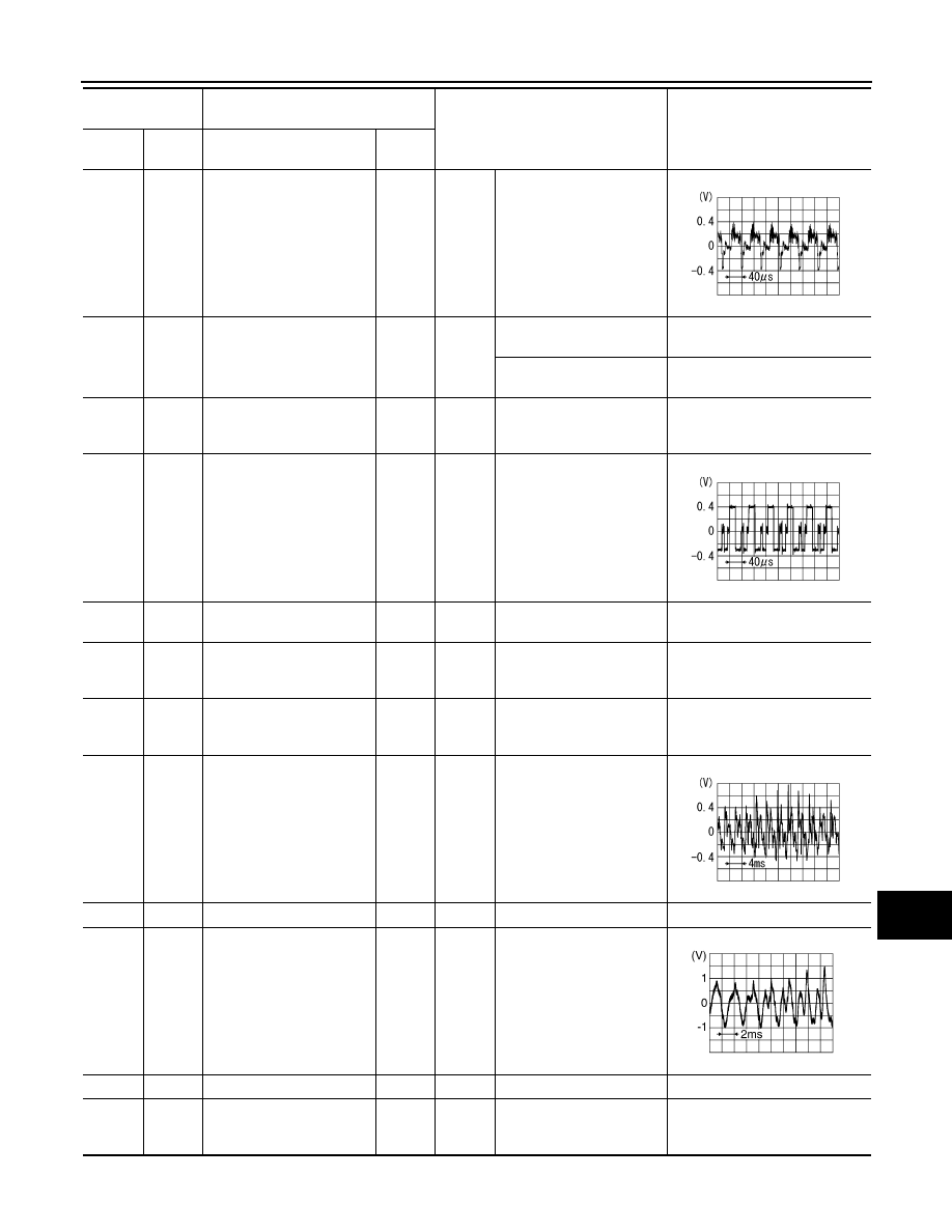
(V)

Ground

Composite (DVD and AUX) 
image signal

Input

Ignition 

switch 

ON

When AUX image is dis-
played.

68

(W)

Ground

Camera connection recog-
nition signal

Input

Ignition 

switch 

ON

Connected to camera con-
trol unit connector 

0 V

Not connected to camera 
control unit connector

5 V

70

(B)

Ground

RGB ground

—

Ignition 

switch 

ON

—

0  V

71

(G)

Ground

RGB image signal (G: 
green)

Input

Ignition 

switch 

ON

Start confirmation/adjust-
ment mode, and then dis-
play color bar by selecting 
“Color Spectrum Bar” on 
Navigation/Phone screen.

73

—

Composite image signal 
ground

—

—

—

—

74

(G)

Ground

Composite (DVD and AUX) 
image signal ground

—

Ignition 

switch 

ON

—

0  V

78

(BR)

Ground

Switch ground

—

Ignition 

switch 

ON

—

0  V

80

(B)

79

(W)

TEL voice signal

Input

Ignition 

switch 

ON

TEL voice output.

81

—

Tel voice shield

—

—

—

—

83

(R)

82

(W)

Stereo (DVD and AUX) 
sound signal RH

Input

Ignition 

switch 

ON

DVD sound signal or AUX 
sound signal input

84

—

Voice guidance shield

—

—

—

—

85

(B/W)

Ground

Ground

—

Ignition 

switch 

ON 

—

0  V

Terminal

(Wire color)

Description

Condition

Reference value

(Approx.)

+

–

Signal name

Input/

Output

SKIB2251J

SKIB2236J

SKIB1990E

SKIB3609E

AV-500

< ECU DIAGNOSIS >

[BOSE AUDIO WITH NAVIGATION]

AV CONTROL UNIT

86

(L)

—

CAN–H

Input/

Output

—

—

—

87

(P)

—

CAN–L

Input/

Output

—

—

—

88

(W)

—

AV communication signal 
(H)

Input/

Output

—

—

—

89

(B)

—

AV communication signal 
(L)

Input/

Output

—

—

—

90

(L)

—

AV communication signal 
(H)

Input/

Output

—

—

—

91

(R)

—

AV communication signal 
(L)

Input/

Output

—

—

—

99

(B)

98

(G)

Stereo (DVD and AUX) 
sound signal LH

Input

Ignition 

switch 

ON

DVD sound signal or AUX 
sound input.

100

—

Stereo (DVD and AUX) 
sound signal shield

—

—

—

—

102

(L)

101

(P)

Voice guidance signal

Input

Ignition 

switch 

ON

Voice guidance output.

103

(SB)

Ground

Disk eject signal

Input

Ignition 

switch 

ON

Pressing the eject switch.

0 V

Except for above.

3.3 V

104

(O)

Ground

Ignition signal

Input

Ignition 

switch 

ON

—

Battery voltage

105

(P/B)

Ground

Reverse signal

Input

Ignition 

switch 

ON

R position.

12.0 V

Other than R position.

0 V

106

(G/R)

Ground

Parking brake signal

Input

Ignition 

switch 

ON

Parking brake ON.

0 V

Parking brake OFF.

5 V

107

(V/W)

Ground

Vehicle speed signal
 (8-pulse)

Input

Ignition 

switch 

ON

When vehicle speed is ap-
prox. 40 km/h (25MPH).

NOTE:

The maximum voltage varies de-

pending on the specification 

(destination unit).

Terminal

(Wire color)

Description

Condition

Reference value

(Approx.)

+

–

Signal name

Input/

Output

SKIB3609E

SKIB1990E

JSNIA0012GB

AV

AV CONTROL UNIT

AV-501

< ECU DIAGNOSIS >

[BOSE AUDIO WITH NAVIGATION]

C

D

E

F

G

H

I

J

K

L

M

B

A

O

P

109
(W)

115

(B)

Stereo sound signal front 
RH

Output

Ignition 

switch 

ON

Sound output.

111

—

Shield

—

—

—

—

112

(BR)

118

(Y)

Voice guidance signal

Output

Ignition 

switch 

ON

Voice guidance output.

113
(W)

119

(B)

Stereo sound signal front 
LH

Output

Ignition 

switch 

ON

Sound output.

Terminal

(Wire color)

Description

Condition

Reference value

(Approx.)

+

–

Signal name

Input/

Output

SKIB3609E

SKIB1990E

SKIB3609E

AV-502

< ECU DIAGNOSIS >

[BOSE AUDIO WITH NAVIGATION]

AV CONTROL UNIT

Wiring Diagram — BOSE AUDIO WITH NAVIGATION SYSTEM —

INFOID:0000000003971962

JCNWM0897GB


Content   ..  159  160  161  162   ..