Content .. 1165 1166 1167 1168 ..
Nissan Teana J32. Manual - part 1167
TM-192
< FUNCTION DIAGNOSIS >
[CVT: RE0F10A]
CONTROL SYSTEM
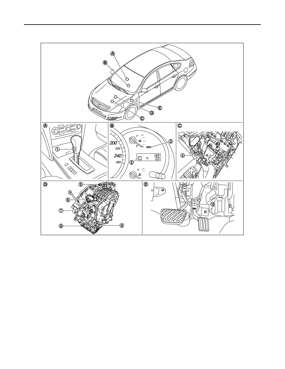
Component Parts Location
INFOID:0000000003809653
*: Control valve assembly is included in CVT assembly.
NOTE:
The following components are included in control valve assembly (8).
• CVT fluid temperature sensor
• Torque converter clutch solenoid valve
• Line pressure solenoid valve
• Step motor
• ROM assembly
• Secondary pressure sensor
• Secondary pressure solenoid valve
• Lock-up select solenoid valve
1.
Sport mode switch
2.
Shift position indicator
3.
SPORT indicator lamp
4.
TCM
5.
Secondary speed sensor
6.
PNP switch
7.
Primary speed sensor
8.
Control valve assembly
*
9.
CVT unit connector
10. Accelerator pedal position sensor
A.
Center console
B.
Combination meter
C.
Engine room LH
D.
CVT assembly
E.
Accelerator pedal, upper
JPDIA0746ZZ