Content .. 1159 1160 1161 1162 ..
Nissan Teana J32. Manual - part 1161
TM-168
< REMOVAL AND INSTALLATION >
[CVT: RE0F09B]
TRANSAXLE ASSEMBLY
REMOVAL AND INSTALLATION
TRANSAXLE ASSEMBLY
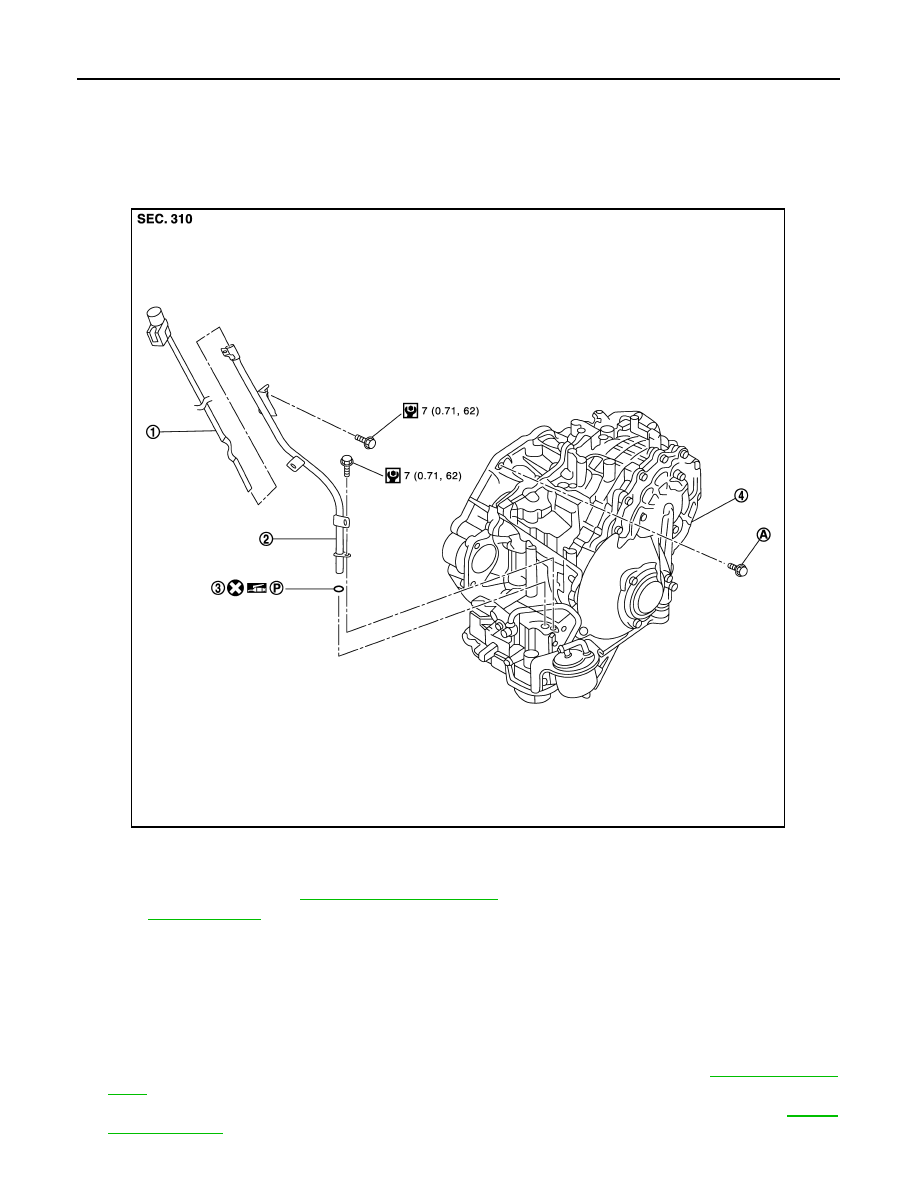
Exploded View
INFOID:0000000003849108
Removal and Installation
INFOID:0000000003849109
WARNING:
Never remove the reservoir tank cap when the engine is hot. Serious burns could occur from high
pressure engine coolant escaping from the reservoir tank.
REMOVAL
1.
Remove the engine, the transaxle assembly and front suspension member. Refer to
.
2.
Lift with hoist and separate engine, transaxle assembly from front suspension member. Refer to
1.
CVT fluid level gauge
2.
CVT fluid charging pipe
3.
O-ring
4.
Transaxle assembly
A.
For tightening torque, refer to
TM-168, "Removal and Installation"
.
for symbols in the figure.
JPDIA0799GB