Content .. 1099 1100 1101 1102 ..
Nissan Teana J32. Manual - part 1101
STEERING WHEEL
ST-11
< ON-VEHICLE MAINTENANCE >
C
D
E
F
H
I
J
K
L
M
A
B
ST
N
O
P
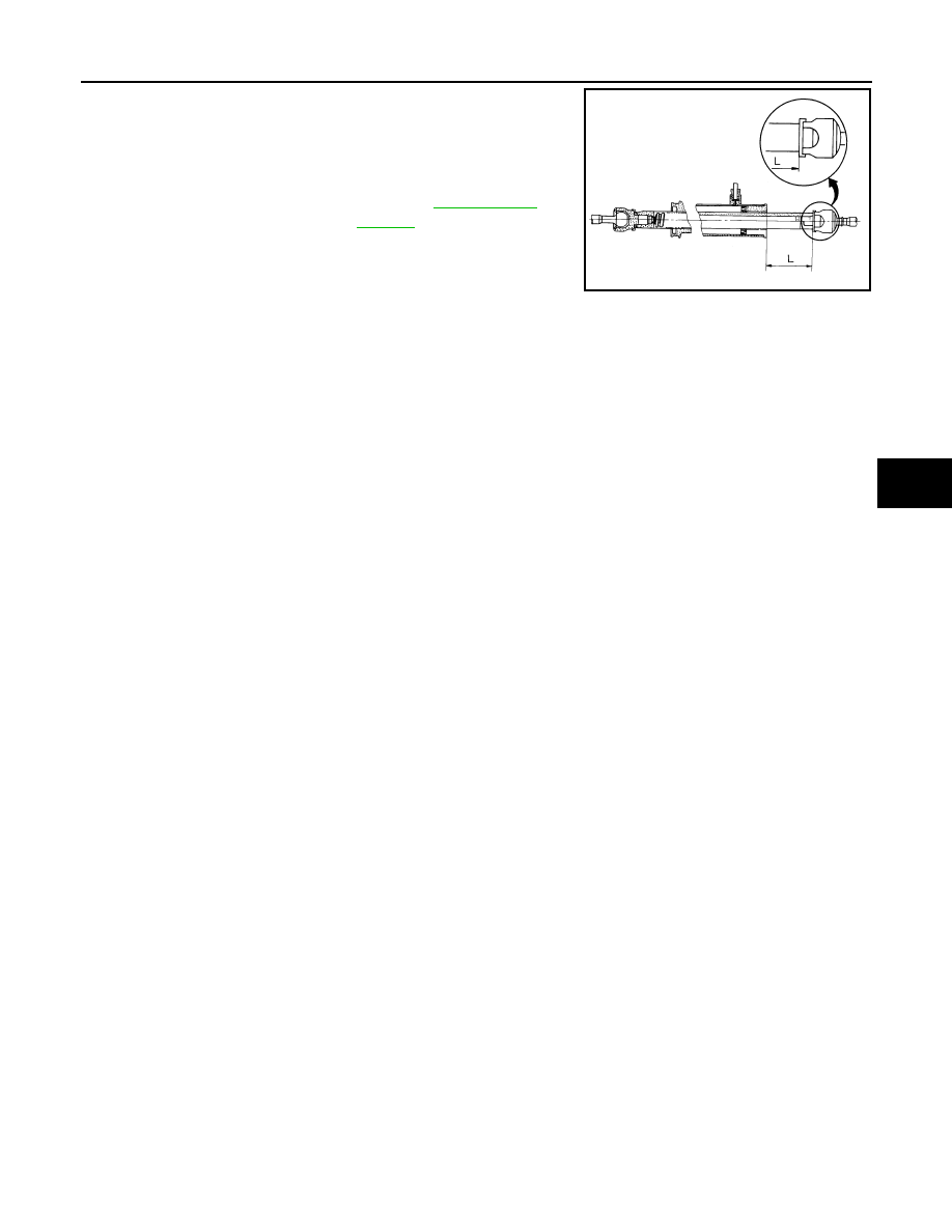
5.
Check the following items when turning angle is out of the stan-
dard.
a.
Check the neutral position of the rack stroke (L).
b.
Disassemble steering gear assembly to check the cause that
rack stroke is outside of the standard.
• Steering angles are not adjustable. Check steering gear
assembly, steering column assembly and front suspension
components for wear or damage if any of the turning angles are different from the specified value.
Replace any of them, if any non-standard condition exists.
Standard
L
: Refer to
.
SGIA0629J