Nissan Teana J32. Manual - part 101


  Index      Nissan     Nissan Teana J32 (2008 year) - Service and Repair Manual


Search            


Content   ..  99  100  101  102   ..


Nissan Teana J32. Manual - part 101


AV

STEERING SWITCH SIGNAL GND CIRCUIT

AV-259

< COMPONENT DIAGNOSIS >

[BOSE AUDIO WITHOUT NAVIGATION]

C

D

E

F

G

H

I

J

K

L

M

B

A

O

P

STEERING SWITCH SIGNAL GND CIRCUIT

Description

INFOID:0000000003765735

Transmits the steering switch signal to AV control unit.

Diagnosis Procedure

INFOID:0000000003765736

1.

CHECK STEERING SWITCH SIGNAL GND CIRCUIT

1.

Turn ignition switch OFF.

2.

Disconnect AV control unit connector and spiral cable connector. 

3.

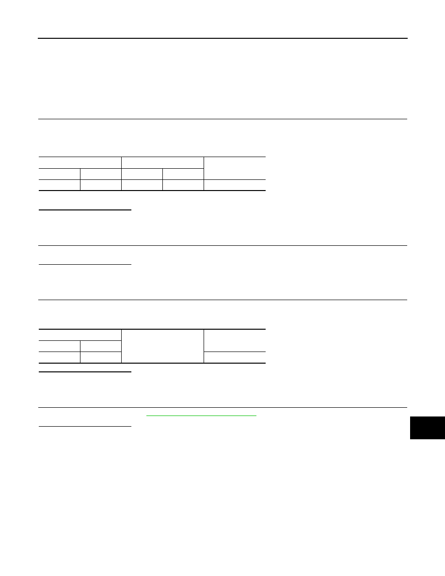
Check continuity between AV control unit harness connector and spiral cable harness connector.

4.

Connect AV control unit connector.

Is inspection result normal?

YES

>> GO TO 2.

NO

>> Repair harness or connector.

2.

CHECK SPIRAL CABLE

Check spiral cable. 

Is inspection result normal?

YES

>> GO TO 3. 

NO

>> Replace spiral cable.

3.

CHECK GROUND CIRCUIT

1.

Connect AV control unit connector.

2.

Check continuity between AV control unit harness connector and ground.

Is inspection result normal?

YES

>> GO TO 4.

NO

>> Replace AV control unit.

4.

CHECK STEERING SWITCH

Check steering switch. Refer to 

AV-260, "Component Inspection"

.

Is inspection result normal?

YES

>> INSPECTION END

NO

>> Replace steering switch.

AV control unit

Spiral cable

Continuity

Connector

Terminal

Connector

Terminal

M127

15

M33

33

Existed

AV control unit

Ground

Continuity

Connector

Terminal

M127

15

Existed

AV-260

< COMPONENT DIAGNOSIS >

[BOSE AUDIO WITHOUT NAVIGATION]

STEERING SWITCH SIGNAL GND CIRCUIT

Component Inspection

INFOID:0000000003765737

Measure the resistance between the steering switch connector ter-
minals 14 to 17 and 15 to 17.

Standard

JSNIA0215GB

Steering switch

Condition

Resistance 

Con-

nector

Termi-

nal

Con-

nector

Termi-

nal

M303

14

M303

17

MENU DOWN switch 
ON

315 – 327

MENU UP switch ON

119 – 123

SOURCE switch ON

1

15

VOL UP switch ON

119 – 123

VOL DOWN switch ON

1

AV

AV CONTROL UNIT

AV-261

< ECU DIAGNOSIS >

[BOSE AUDIO WITHOUT NAVIGATION]

C

D

E

F

G

H

I

J

K

L

M

B

A

O

P

ECU DIAGNOSIS

AV CONTROL UNIT

Reference Value

INFOID:0000000003765757

VALUES ON THE DIAGNOSIS TOOL

CONSULT-III data monitor item

TERMINAL LAYOUT

PHYSICAL VALUES

Display Item

Dis-
play

Vehicle status

Remarks

VHCL SPD SIG

On

Vehicle speed >0 km/h (0 MPH)

Changes in indication may be delayed. This is nor-
mal.

Off

Vehicle speed =0 km/h (0 MPH)

PKB SIG

On

Parking brake is applied.

Changes in indication may be delayed. This is nor-
mal.

Off

Parking brake is released.

ILLUM SIG

On

Light switch ON.

Off

Light switch OFF.

IGN SIG

On

Ignition switch ON.

Off

Ignition switch in ACC position.

REV SIG

On

Selector lever in R position.

Changes in indication may be delayed. This is nor-
mal.

Off

Selector lever in any position other 
than R.

JPNIA1093ZZ

Terminal

(Wire color)

Description

Condition

Reference value

(Approx.)

+

Signal name

Input/

Output

6

(W/G)

15

(L/B)

Steering switch signal A

Input

Ignition 

switch 

ON

Keep pressing SOURCE 
switch.

 0 V

Keep pressing 

 switch.

0.7 V

Keep pressing 

 switch.

1.3 V

Except for above.

3.3 V

7

(V/W)

Ground

ACC power supply

Input

Ignition 

switch 

ACC

Battery voltage

9

(R/L)

Ground

Illumination signal

Input

Ignition 

switch 

OFF

Lighting switch is OFF.

0 V

Lighting switch is ON.

12.0 V

AV-262

< ECU DIAGNOSIS >

[BOSE AUDIO WITHOUT NAVIGATION]

AV CONTROL UNIT

15

(L/B)

Ground

Steering switch signal 
ground

Ignition 

switch 

ON

0  V

16

(GR/L)

15

(L/B)

Steering switch signal B

Input

Ignition 

switch 

ON

Keep pressing VOL DOWN 
switch.

0 V

Keep pressing VOL UP 
switch.

0.7 V

Except for above.

3.3 V

19

(Y)

Ground

Battery power supply

Input

Ignition 

switch 

OFF

Battery voltage

20

(B/W)

Ground

Ground

Ignition 

switch 

ON

0  V

33

FM sub

Input

34

AM–FM main

Input

35

Ground

Antenna amp. ON signal

Output

Ignition 

switch 

ACC

12.0 V

36

(B)

Ground

Composite image signal

Output

Ignition 

switch 

ON

When camera image, DVD 
image or AUX image is dis-
played.

37

(W)

Ground

Composite image signal 
ground

Ignition 

switch 

ON

0  V

38

(B)

Ground

RGB image signal (B: blue)

Output

Ignition 

switch 

ON

Start confirmation/adjust-
ment mode, and then dis-
play color bar by selecting 
“Color Spectrum Bar” on 
DISPLAY DIAGNOSIS 
screen.

39

(R)

Ground

RGB image signal (G: 
green)

Output

Ignition 

switch 

ON

Start confirmation/adjust-
ment mode, and then dis-
play color bar by selecting 
“Color Spectrum Bar” on 
DISPLAY DIAGNOSIS 
screen.

Terminal

(Wire color)

Description

Condition

Reference value

(Approx.)

+

Signal name

Input/

Output

SKIB2251J

SKIB2237J

SKIB2236J


Content   ..  99  100  101  102   ..