Nissan Teana J32. Manual - part 99
AV
CAMERA IMAGE SIGNAL CIRCUIT
AV-251
< COMPONENT DIAGNOSIS >
[BOSE AUDIO WITHOUT NAVIGATION]
C
D
E
F
G
H
I
J
K
L
M
B
A
O
P
CAMERA IMAGE SIGNAL CIRCUIT
Description
INFOID:0000000003765723
• Camera control unit outputs camera ON signal to rear view camera and inputs rear view camera image sig-
nal from rear view camera when the reverse signal is input.
• The camera control unit that inputs the camera image signal transmits the camera image signal to the AV
control unit.
Diagnosis Procedure
INFOID:0000000003901195
1.
CHECK CONTINUITY CAMERA IMAGE SIGNAL CIRCUIT
1.
Turn ignition switch OFF.
2.
Disconnect camera control unit connector and AV control unit connector.
3.
Check continuity between camera control unit harness connector and AV control unit harness connector.
4.
Check continuity between camera control unit harness connector and ground.
Is inspection result normal?
YES
>> GO TO 2.
NO
>> Repair harness or connector.
2.
CHECK CAMERA IMAGE SIGNAL
1.
Connect camera control unit connector and AV control unit connector.
2.
Turn ignition switch ON.
3.
Check signal between camera control unit harness connector using an oscilloscope.
Is inspection result normal?
YES
>> Replace AV control unit.
NO
>> Replace camera control unit.
Camera control unit
AV control unit
Continuity
Connector
Terminals
Connector
Terminals
B251
11
M130
64
Existed
12
65
Camera control unit
Ground
Continuity
Connector
Terminal
B251
12
Not existed
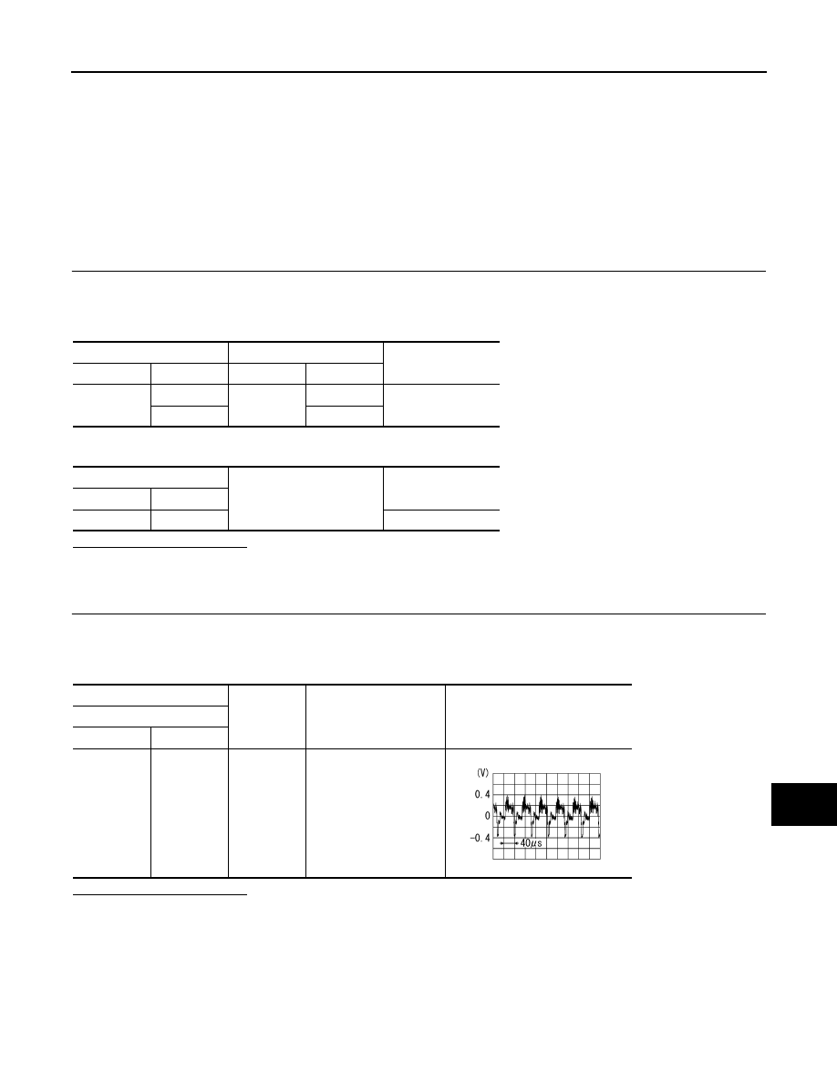
(+)
(
−
)
Condition
Reference value
Camera control unit
Connector
Terminal
B251
12
Ground
When rear view camera
image is displayed.
SKIB2251J