Nissan Teana J32. Manual - part 59


  Index      Nissan     Nissan Teana J32 (2008 year) - Service and Repair Manual


Search            


Content   ..  57  58  59  60   ..


Nissan Teana J32. Manual - part 59


AV

HORIZONTAL SYNCHRONIZING (HP) SIGNAL CIRCUIT

AV-91

< COMPONENT DIAGNOSIS >

[BASE AUDIO AND DISPLAY SYSTEM]

C

D

E

F

G

H

I

J

K

L

M

B

A

O

P

HORIZONTAL SYNCHRONIZING (HP) SIGNAL CIRCUIT

Description

INFOID:0000000003882749

In composite image (AUX image, camera image), transmit the vertical synchronizing (VP) signal and horizon-
tal synchronizing (HP) signal from display unit to AV control unit so as to synchronize the RGB images dis-
played with AV control unit such as the image quality adjusting menu, etc.

Diagnosis Procedure

INFOID:0000000003901211

1.

CHECK CONTINUITY HORIZONTAL SYNCHRONIZING (HP) SIGNAL CIRCUIT

1.

Turn ignition switch OFF.

2.

Disconnect display unit connector and AV control unit connector.

3.

Check continuity between display unit harness connector and AV control unit harness connector.

4.

Check continuity between display unit harness connector and ground.

Is inspection result normal?

YES

>> GO TO 2.

NO

>> Repair harness or connector.

2.

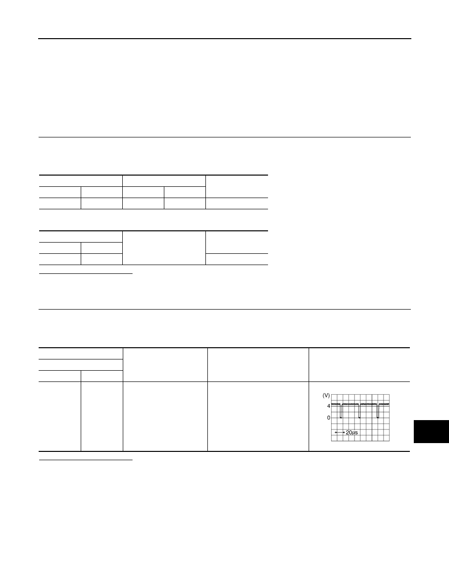
CHECK HORIZONTAL SYNCHRONIZING (HP) SIGNAL

1.

Connect display unit connector and AV control unit connector.

2.

Turn ignition switch ON.

3.

Check signal between display unit harness connector terminal and ground using an oscilloscope.

Is inspection result normal?

YES

>> Replace AV control unit.

NO

>> Replace display unit.

Display unit

AV control unit

Continuity

Connector

Terminal

Connector

Terminal

M49

8

M129

45

Existed

Display unit

Ground

Continuity

Connector

Terminal

M49

8

Not existed

(+)

(

)

Condition

Reference value

Display unit

Connector

Terminal

M49

8

Ground

SKIB3601E

AV-92

< COMPONENT DIAGNOSIS >

[BASE AUDIO AND DISPLAY SYSTEM]

VERTICAL SYNCHRONIZING (VP) SIGNAL CIRCUIT

VERTICAL SYNCHRONIZING (VP) SIGNAL CIRCUIT

Description

INFOID:0000000003882751

In composite image (AUX image, camera image), transmit the vertical synchronizing (VP) signal and horizon-
tal synchronizing (HP) signal from display unit to AV control unit so as to synchronize the RGB images dis-
played with AV control unit such as the image quality adjusting menu, etc.

Diagnosis Procedure

INFOID:0000000003901212

1.

CHECK CONTINUITY VERTICAL SYNCHRONIZING (VP) SIGNAL CIRCUIT

1.

Turn ignition switch OFF.

2.

Disconnect display unit connector and AV control unit connector.

3.

Check continuity between display unit harness connector and AV control unit harness connector.

4.

Check continuity between display unit harness connector and ground.

Is inspection result normal?

YES

>> GO TO 2.

NO

>> Repair harness or connector.

2.

CHECK VERTICAL SYNCHRONIZING (VP) SIGNAL

1.

Connect display unit connector and AV control unit connector.

2.

Turn ignition switch ON.

3.

Check signal between display unit harness connector terminal and ground using an oscilloscope.

Is inspection result normal?

YES

>> Replace AV control unit.

NO

>> Replace display unit.

Display unit

AV control unit

Continuity

Connector

Terminal

Connector

Terminal

M49

20

M129

57

Existed

Display unit

Ground

Continuity

Connector

Terminal

M49

20

Not existed

(+)

(

)

Condition

Reference value

Display unit

Connector

Terminal

M49

20

Ground

SKIB3598E

AV

AUX IMAGE SIGNAL CIRCUIT

AV-93

< COMPONENT DIAGNOSIS >

[BASE AUDIO AND DISPLAY SYSTEM]

C

D

E

F

G

H

I

J

K

L

M

B

A

O

P

AUX IMAGE SIGNAL CIRCUIT

Description

INFOID:0000000003882753

Transmits the image signal of external device from auxiliary input jacks to AV control unit.

Diagnosis Procedure

INFOID:0000000003882754

1.

CHECK CONTINUITY AUX IMAGE SIGNAL CIRCUIT

1.

Turn ignition switch OFF.

2.

Disconnect auxiliary input jacks connector and AV control unit connector.

3.

Check continuity between auxiliary input jacks harness connector and AV control unit harness connector.

4.

Check continuity between auxiliary input jacks harness connector and ground.

Is inspection result normal?

YES

>> GO TO 2.

NO

>> Repair harness or connector.

2.

CHECK AUX IMAGE SIGNAL

1.

Connect auxiliary input jacks connector and AV control unit connector.

2.

Turn ignition switch ON.

3.

Make AUX image signal being input.

4.

Check signal between auxiliary input jacks harness connector using an oscilloscope.

Is inspection result normal?

YES

>> Replace AV control unit.

NO

>> Check that there is no malfunction in the external device.

Auxiliary input jacks

AV control unit

Continuity

Connector

Terminals

Connector

Terminals

M253

7

M130

66

Existed

8

74

Auxiliary input jacks

Ground

Continuity

Connector

Terminal

M253

7

Not existed

(+)

(

)

Condition

Reference value

Auxiliary input jacks

Auxiliary input jacks

Connector

Terminal

Connector

Terminal

M253

7

M253

8

When AUX image is displayed.

SKIB2251J

AV-94

< COMPONENT DIAGNOSIS >

[BASE AUDIO AND DISPLAY SYSTEM]

DISK EJECT SIGNAL CIRCUIT

DISK EJECT SIGNAL CIRCUIT

Description

INFOID:0000000003882755

The eject signal is output to AV control unit when the eject switch of multifunction switch is pressed.

Diagnosis Procedure

INFOID:0000000003901213

1.

CHECK CONTINUITY DISK EJECT SIGNAL CIRCUIT

1.

Turn ignition switch OFF.

2.

Disconnect multifunction switch connector and AV control unit connector.

3.

Check continuity between multifunction switch harness connector and AV control unit harness connector.

4.

Check continuity between multifunction switch harness connector and ground.

Is inspection result normal?

YES

>> GO TO 2.

NO

>> Repair harness or connector.

2.

CHECK AV CONTROL UNIT VOLTAGE 

1.

Connect multifunction switch connector and AV control unit connector.

2.

Turn ignition switch ON.

3.

Check voltage between AV control unit harness connector and ground.

Is inspection result normal?

YES

>> Replace preset switch.

NO

>> Replace AV control unit.

Multifunction switch

AV control unit

Continuity

Connector

Terminal

Connector

Terminal

M125

14

M131

103

Existed

Multifunction switch

Ground

Continuity

Connector

Terminal

M125

14

Not existed

(+)

(

)

Condition

Reference value

AV control unit

Connector

Terminal

M131

103

Ground

Pressing the eject switch.

0 V

Except for above.

3.3 V


Content   ..  57  58  59  60   ..