Nissan Teana J32. Manual - part 57
AV
POWER SUPPLY AND GROUND CIRCUIT
AV-83
< COMPONENT DIAGNOSIS >
[BASE AUDIO AND DISPLAY SYSTEM]
C
D
E
F
G
H
I
J
K
L
M
B
A
O
P
2.
CHECK GROUND CIRCUIT
1.
Turn ignition switch OFF.
2.
Disconnect the harness connector between display unit and AV control unit.
3.
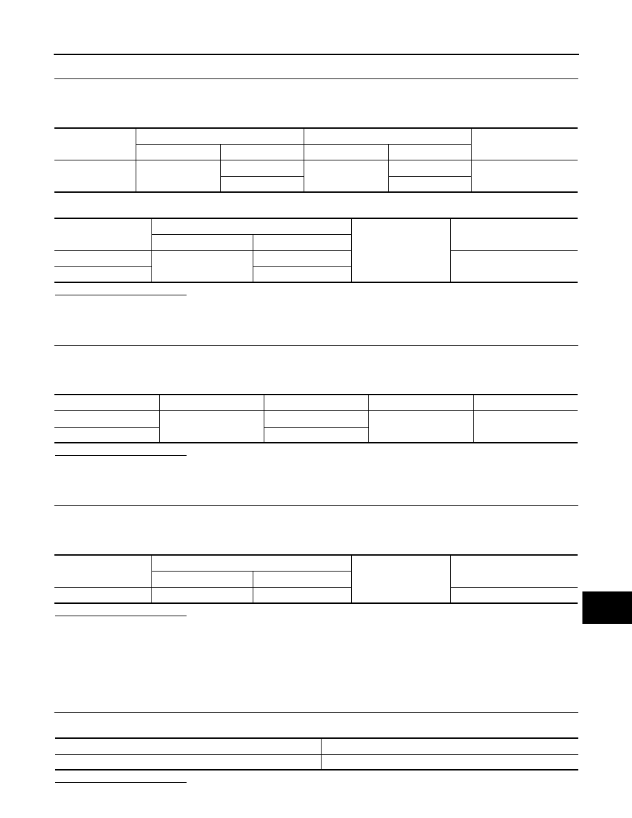
Check continuity between display unit harness connector and AV control unit harness connector.
4.
Check continuity between display unit harness connector and ground.
Is inspection result normal?
YES
>> GO TO 3.
NO
>> Repair harness or connector.
3.
CHECK POWER SUPPLY CIRCUIT (AV CONTROL UNIT SIDE)
1.
Connect the AV control unit harness connector.
2.
Turn ignition switch ACC.
3.
Check voltage between AV control unit harness connector and ground.
Is inspection result normal?
YES
>> INSPECTED END.
NO
>> Replace AV control unit.
4.
CHECK GROUND CIRCUIT
1.
Turn ignition switch OFF.
2.
Disconnect display unit connector.
3.
Check continuity between display unit harness connector and ground.
Is inspection result normal?
YES
>> INSPECTED END.
NO
>> Repair harness or connector.
MULTIFUNCTION SWITCH
MULTIFUNCTION SWITCH : Diagnosis Procedure
INFOID:0000000003901204
1.
CHECK FUSE
Check for blown fuses.
Is inspection result normal?
Signal name
Display unit
AV control unit
Continuity
Connector No.
Terminal No.
Connector No.
Terminal No.
Ground
M49
2
M129
59
Existed
3
47
Signal name
Display unit
Ground
Continuity
Connector No.
Terminal No.
Inverter VCC
M49
2
Not existed
Signal VCC
3
Signal name
Connector No.
Terminal No.
Ignition switch position
Voltage (Approx.)
Inverter VCC
M129
59
ACC
9 V
Signal VCC
47
Signal name
Display unit
Ground
Continuity
Connector No.
Terminal No.
Ground
M49
1
Existed
Power source
Fuse No.
Ignition switch ACC or ON
19