Nissan Teana J32. Manual - part 42
AV
STEERING SWITCH SIGNAL B CIRCUIT
AV-23
< COMPONENT DIAGNOSIS >
[AUDIO SYSTEM]
C
D
E
F
G
H
I
J
K
L
M
B
A
O
P
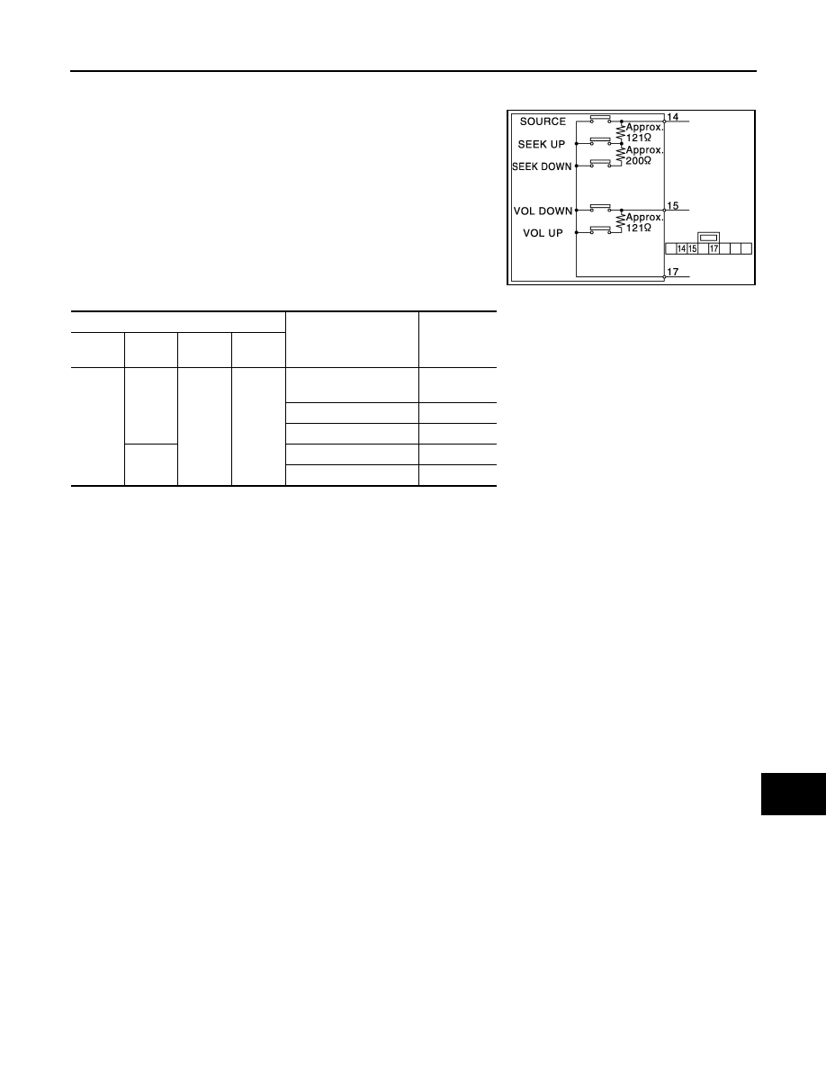
Component Inspection
INFOID:0000000003765599
Measure the resistance between the steering switch connector ter-
minals.
Standard
JSNIA1145GB
Steering switch
Condition
Resistance
Ω
Con-
nector
Termi-
nals
Con-
nector
Termi-
nal
M303
14
M303
17
SEEK DOWN switch
ON
315 – 327
SEEK UP switch ON
119 – 123
SOURCE switch ON
0
15
VOL UP switch ON
119 – 123
VOL DOWN switch ON
0