содержание .. 902 903 904 905 ..
Nissan Murano Z51. Manual - part 904
DIAGNOSIS SYSTEM (BCM)
INL-17
< SYSTEM DESCRIPTION >
C
D
E
F
G
H
I
J
K
M
A
B
INL
N
O
P
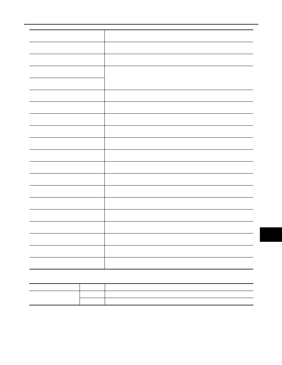
ACTIVE TEST
*: Each lamp switch is in ON position.
Monitor item
[Unit]
Description
REQ SW-DR
[On/Off]
The switch status input from request switch (driver side)
REQ SW-AS
[On/Off]
The switch status input from front request switch (passenger side)
REQ SW-RR
[On/Off]
NOTE:
The item is indicated, but not monitored.
REQ SW-RL
[On/Off]
PUSH SW
[On/Off]
The switch status input from push-button ignition switch
KEY SW-SLOT
[On/Off]
Key switch status input from key slot
UNLK SEN-DR
[On/Off]
Driver door unlock status input from unlock sensor
DOOR SW-DR
[On/Off]
The switch status input from front door switch (driver side)
DOOR SW-AS
[On/Off]
The switch status input from front door switch (passenger side)
DOOR SW-RR
[On/Off]
The switch status input from rear door switch RH
DOOR SW-RL
[On/Off]
The switch status input from rear door switch LH
DOOR SW-BK
[On/Off]
NOTE:
The item is indicated, but not monitored.
CDL LOCK SW
[On/Off]
Lock switch status received from door lock/unlock switch by power window switch se-
rial link
CDL UNLOCK SW
[On/Off]
Unlock switch status received from door lock/unlock switch by power window switch
serial link
KEY CYL LK-SW
[On/Off]
Lock switch status received from key cylinder lock/unlock switch by power window
switch serial link
KEY CYL UN-SW
[On/Off]
Unlock switch status received from key cylinder lock/unlock switch by power window
switch serial link
BACK DOOR SW
[On/Off]
The switch status input from back door switch
RKE-LOCK
[On/Off]
Lock signal status received from remote keyless entry receiver
RKE-UNLOCK
[On/Off]
Unlock signal status received from remote keyless entry receiver
Test item
Operation
Description
BATTERY SAVER
Off
Cuts the interior room lamp power supply to turn interior room lamp OFF.
On
Outputs the interior room lamp power supply to turn interior room lamp ON.*