содержание .. 877 878 879 880 ..
Nissan Murano Z51. Manual - part 879
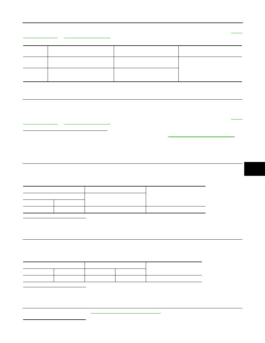
B2578, B2579 IN-VEHICLE SENSOR
HAC-171
< DTC/CIRCUIT DIAGNOSIS >
[WITH 7 INCH DISPLAY]
C
D
E
F
G
H
J
K
L
M
A
B
HAC
N
O
P
NOTE:
If DTC is displayed along with DTC U1000 or U1010, first diagnose the DTC U1000 or U1010. Refer to
DTC CONFIRMATION PROCEDURE
1.
CHECK WITH SELF-DIAGNOSIS FUNCTION OF CONSULT-III
1.
Using CONSULT-III, perform “SELF-DIAGNOSIS RESULTS” of HVAC.
2.
Check if any DTC No. is displayed in the self-diagnosis results.
NOTE:
If DTC is displayed along with DTC U1000 or U1010, first diagnose the DTC U1000 or U1010. Refer to
Is DTC No.“B2578” or “B2579” displayed?
YES
>> Perform trouble diagnosis for the in-vehicle sensor. Refer to
HAC-171, "Diagnosis Procedure"
.
NO
>> INSPECTION END
Diagnosis Procedure
INFOID:0000000005514712
1.
CHECK VOLTAGE BETWEEN IN-VEHICLE SENSOR AND GROUND
1.
Disconnect in-vehicle sensor connector.
2.
Turn ignition switch ON.
3.
Check voltage between in-vehicle sensor harness connector and ground.
Is the inspection result normal?
YES
>> GO TO 2.
NO
>> GO TO 4.
2.
CHECK CIRCUIT CONTINUITY BETWEEN IN-VEHICLE SENSOR AND A/C AUTO AMP.
1.
Turn ignition switch OFF.
2.
Disconnect A/C auto amp. connector.
3.
Check continuity between in-vehicle sensor harness connector and A/C auto amp. harness connector.
Is the inspection result normal?
YES
>> GO TO 3.
NO
>> Repair harness or connector.
3.
CHECK IN-VEHICLE SENSOR
Check in-vehicle sensor. Refer to
HAC-172, "Component Inspection"
.
Is the inspection result normal?
YES
>> Replace A/C auto amp.
DTC
Items
(CONSULT-III screen terms)
Diagnostic item is detected when...
Possible cause
B2578
IN CAR SEN SHORT
Detected temperature at in-vehicle
sensor
−
44
°
C (
−
47
°
F) or less
• In-vehicle sensor
• A/C auto amp.
• Harness and connector
(In-vehicle sensor circuit is open,
or there is a short in the circuit)
B2579
IN CAR SEN OPEN
Detected temperature at in-vehicle
sensor 100
°
C (212
°
F) or more
(+)
(
−
)
Voltage
In-vehicle sensor
—
Connector
Terminal
M41
1
Ground
Approx. 5 V
In-vehicle sensor
A/C auto amp.
Continuity
Connector
Terminal
Connector
Terminal
M41
2
M50
37
Existed