Nissan Murano Z51. Manual - part 877


  Главная      Nissan     Nissan Murano Z51 (2010 year) - Service Manual


поиск по сайту            


содержание   ..  875  876  877  878   ..


Nissan Murano Z51. Manual - part 877


DIAGNOSIS SYSTEM (HVAC)

HAC-163

< SYSTEM DESCRIPTION >

[WITH 7 INCH DISPLAY]

C

D

E

F

G

H

J

K

L

M

A

B

HAC

N

O

P

ACTIVE TEST

HVAC TEST

NOTE:

Perform the inspection of each output device after starting the engine because the compressor is operated. 

WORK SUPPORT

AMB SEN CAL

[

°

C]

Ambient sensor value calculated by A/C auto amp.

IN-VEH CAL

[

°

C]

In-vehicle sensor value calculated by A/C auto amp.

INT TEMP CAL

[

°

C]

Intake sensor value calculated by A/C auto amp.

SUNL SEN CAL

[w/m

2

]

Sunload sensor value calculated by A/C auto amp.

FAN DUTY

Duty ratio of blower motor judged by A/C auto amp.

XM

Target discharge air temperature judged by A/C auto amp. according to the tempera-
ture setting and the value from each sensor

ENG COOL TEMP

[

°

C]

Water temperature signal value received from ECM via CAN communication

VEHICLE SPEED

[Mph

(km/h)]

Vehicle speed signal value received from meter via CAN communication

Monitor item [Unit]

Description

Test item

Description

ALL SEG

NOTE:
• Item can be displayed but cannot be tested.
• When choosing to turn “ALL SEG” on, error message is displayed but it is not malfunction.
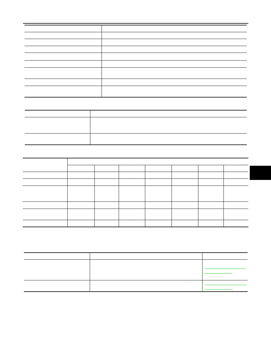
HVAC TEST

The operation check of A/C system can be performed by selecting the mode.  Refer to the 
following table for the conditions of each mode.

Test item

MODE 1

MODE 2

MODE 3

MODE 4

MODE 5

MODE 6

MODE 7

Mode door position

VENT1

VENT2

B/L1

B/L2

FOOT

D/F

DEF

Intake door position

REC

REC

20%FRE

20%FRE

FRE

FRE

FRE

Air mix door position 
(driver & passenger 
side)

FULL COLD

FULL HOT

FULL COLD

FULL HOT

FULL HOT

FULL HOT

FULL HOT

Blower motor duty ratio

35%

35%

61%

61%

81%

81%

35%

Compressor (Magnet 
clutch)

ON

ON

ON

ON

OFF

OFF

ON

Upper ventilator door

OPEN

SHUT

OPEN

SHUT

SHUT

SHUT

SHUT

Work item

Description

Reference

TEMP SET CORRECT
(Setting of difference between tem-
perature setting and control tempera-
ture)

If the temperature felt by the customer is different than the air flow 
temperature controlled by the temperature setting, the auto ampli-
fier control temperature can be adjusted to compensate for the 
temperature setting. 

HAC-131, "Temperature 
Setting Trimmer"

BLOW SET
(Blow setting to DEF in FOOT mode)

In the FOOT mode, the air blowing to the DEF can change ON/
OFF. 

HAC-131, "Foot Position 
Setting Trimmer"

HAC-164

< SYSTEM DESCRIPTION >

[WITH 7 INCH DISPLAY]

DIAGNOSIS SYSTEM (HVAC)

NOTE:

When the battery cable is disconnected from the negative terminal or when the battery voltage becomes 10 V or less, the setting of
WORK SUPPORT may be cancelled. 

FRE MEMORY SET
(FRE memory function setting)

• If the ignition switch is turned to the OFF position while the FRE 

switch is set to ON (fresh air intake), “Perform the memory” or 
“Do not perform the memory” of the FRE switch ON (fresh air in-
take) condition can be selected. 

• If “Perform the memory” was set, the FRE switch will be ON 

(fresh air intake) when turning the ignition switch to the ON posi-
tion again. 

• If “Do not perform the memory” was set, the air inlets will be con-

trolled automatically when turning the ignition switch to the ON 
position again. 

HAC-132, "Inlet Port 
Memory Function (FRE)"

REC MEMORY SET
(REC memory function setting)

• If the ignition switch is turned to the OFF position while the REC 

switch is set to ON (recirculation), “Perform the memory” or “Do 
not perform the memory” of the REC switch ON (recirculation) 
condition can be selected. 

• If “Perform the memory” was set, the REC switch will be ON (re-

circulation) when turning the ignition switch to the ON position 
again. 

• If “Do not perform the memory” was set, the air inlets will be con-

trolled automatically when turning the ignition switch to the ON 
position again. 

HAC-132, "Inlet Port 
Memory Function (REC)"

Work item

Description

Reference

U1000 CAN COMM CIRCUIT

HAC-165

< DTC/CIRCUIT DIAGNOSIS >

[WITH 7 INCH DISPLAY]

C

D

E

F

G

H

J

K

L

M

A

B

HAC

N

O

P

DTC/CIRCUIT DIAGNOSIS

U1000 CAN COMM CIRCUIT

Description

INFOID:0000000005514700

CAN (Controller Area Network) is a serial communication line for real time application. It is an on-vehicle mul-
tiplex communication line with high data communication speed and excellent error detection ability. Many elec-
tronic control units are equipped onto a vehicle, and each control unit shares information and links with other
control units during operation (not independent). In CAN communication, control units are connected with two
communication lines (CAN-H line, CAN-L line) allowing a high rate of information transmission with less wiring.
Each control unit transmits/receives data but selectively reads required data only.
CAN Communication Signal Chart. Refer to 

LAN-16, "How to Use CAN Communication Signal Chart"

.

DTC Logic

INFOID:0000000005514701

DTC DETECTION LOGIC

Diagnosis Procedure

INFOID:0000000005514702

1.

CHECK WITH SELF-DIAGNOSIS FUNCTION OF CONSULT-III

1.

Turn ignition switch ON and wait for 2 or more seconds.

2.

Using CONSULT-III, perform “SFLF-DIAGNOSIS RESULTS” of HVAC. 

Is “CAN COMM CIRCUIT” displayed?

YES

>> Perform trouble diagnosis for the CAN communication system. Refer to 

LAN-17, "Trouble Diagno-

sis Flow Chart"

.

NO

>> Perform the intermittent malfunction diagnosis. Refer to 

GI-39, "Intermittent Incident"

.

DTC

Items

 (CONSULT-III screen terms)

Diagnostic item is detected when...

Possible cause

U1000

CAN COMM CIRCUIT

When A/C auto amp. is not transmitting 
or receiving CAN communication signal 
for 2 or more seconds.

CAN communication system

HAC-166

< DTC/CIRCUIT DIAGNOSIS >

[WITH 7 INCH DISPLAY]

U1010 CONTROL UNIT (CAN)

U1010 CONTROL UNIT (CAN)

Description

INFOID:0000000005514703

Initial diagnosis of A/C auto amp.

DTC Logic

INFOID:0000000005514704

DTC DETECTION LOGIC

Diagnosis Procedure

INFOID:0000000005514705

1.

CHECK WITH SELF-DIAGNOSIS FUNCTION OF CONSULT-III

Using CONSULT-III, perform “SELF-DIAGNOSIS RESULTS” of HVAC. 

Is DTC No.“U1010” displayed?

YES

>> Replace A/C auto amp.

NO

>> INSPECTION END

DTC

Items

 (CONSULT-III screen terms)

Diagnostic item is detected when...

Possible cause

U1010

CONTROL UNIT (CAN)

When detecting error during the initial diag-
nosis of CAN controller of A/C auto amp.

A/C auto amp.


содержание   ..  875  876  877  878   ..