Nissan Murano Z51. Manual - part 863


  Главная      Nissan     Nissan Murano Z51 (2010 year) - Service Manual


поиск по сайту            


содержание   ..  861  862  863  864   ..


Nissan Murano Z51. Manual - part 863


A/C AUTO AMP.

HAC-107

< ECU DIAGNOSIS INFORMATION >

[WITHOUT 7 INCH DISPLAY]

C

D

E

F

G

H

J

K

L

M

A

B

HAC

N

O

P

*: Perform self-diagnosis under sunshine. When performing indoors, aim a light (more than 60 W) at sunload sensor, otherwise self-diag-
nosis indicates even though the sunload sensor is functioning normally.
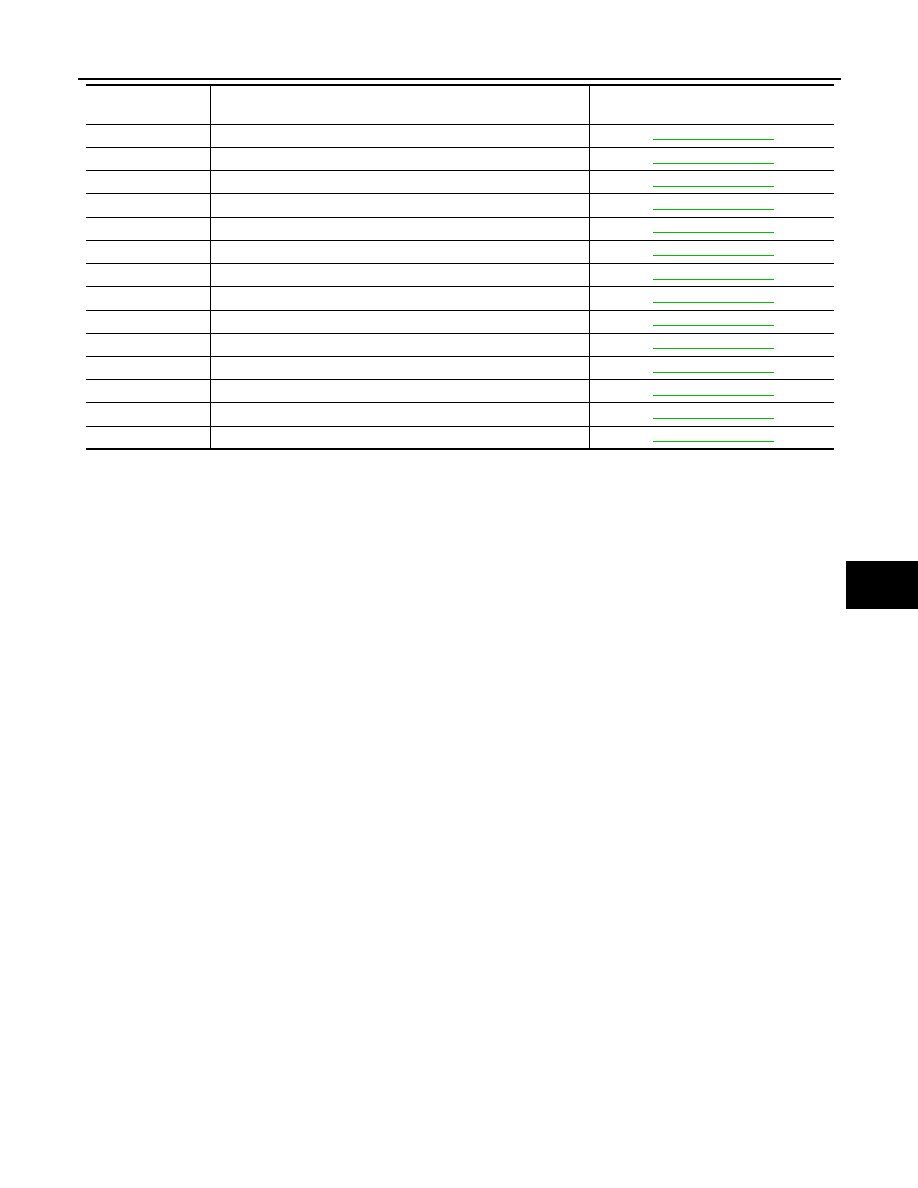
B2634

PASS AIRMIX ACTR SHORT

HAC-59, "DTC Logic"

B2635

PASS AIRMIX ACTR OPEN

HAC-59, "DTC Logic"

B2636

DR VENT DOOR FAIL

HAC-61, "DTC Logic"

B2637

DR B/L DOOR FAIL

HAC-61, "DTC Logic"

B2638

DR D/F1 DOOR FAIL

HAC-61, "DTC Logic"

B2639

DR DEF DOOR FAIL

HAC-61, "DTC Logic"

B263D

FRE DOOR FAIL

HAC-64, "DTC Logic"

B263E

20P FRE DOOR FAIL

HAC-64, "DTC Logic"

B263F

REC DOOR FAIL

HAC-64, "DTC Logic"

B2654

D/F2 DOOR FAIL

HAC-61, "DTC Logic"

B2655

B/L2 DOOR FAIL

HAC-61, "DTC Logic"

B2661

UPPER VENT DOOR OPEN POSI FAIL

HAC-66, "DTC Logic"

B2662

UPPER VENT DOOR MID POSI FAIL

HAC-66, "DTC Logic"

B2663

UPPER VENT DOOR SHUT POSI FAIL

HAC-66, "DTC Logic"

DTC

Items

(CONSULT-III screen terms)

Reference

HAC-108

< SYMPTOM DIAGNOSIS >

[WITHOUT 7 INCH DISPLAY]

AIR CONDITIONER CONTROL

SYMPTOM DIAGNOSIS

AIR CONDITIONER CONTROL

Diagnosis Chart By Symptom

INFOID:0000000005514652

Symptom

Reference

A/C system does not activate.

Go to Trouble Diagnosis Procedure for A/C Control Signal 
Circuit.

HAC-75, "Diagnosis Proce-

dure"

A/C display dose not work.

Go to Trouble Diagnosis Procedure for A/C Display.

HAC-78, "A/C DISPLAY : Diag-

nosis Procedure"


Air outlet does not change.

Go to Trouble Diagnosis Procedure for Mode Door Motor. 
(LAN)

HAC-62, "Diagnosis Proce-

dure"

Mode door motor does not operate 
normally.

Discharge air temperature does not 
change.

Go to Trouble Diagnosis Procedure for Air Mix Door Motor. 
(LAN)

HAC-58, "Diagnosis Proce-

dure"

 (driver side) or 

HAC-60, 

"Diagnosis Procedure"

 (pas-

senger side)

Air mix door motor does not operate 
normally.

Intake door does not change.

Go to Trouble Diagnosis Procedure for Intake Door Motor. 
(LAN)

HAC-65, "Diagnosis Proce-

dure"

Intake door motor does not operate 
normally.

Blower motor operation is malfunc-
tioning.

Go to Trouble Diagnosis Procedure for Blower Motor.

HAC-69, "Diagnosis Proce-

dure"

Magnet clutch does not engage.

Go to Trouble Diagnosis Procedure for Magnet Clutch.

HAC-73, "Diagnosis Proce-

dure"

Insufficient cooling

Go to Trouble Diagnosis Procedure for Insufficient Cooling.

HAC-109, "Inspection proce-

dure"

No cool air comes out.
(Air flow volume is normal.)

Insufficient heating

Go to Trouble Diagnosis Procedure for Insufficient Heating.

HAC-112, "Inspection proce-

dure"

No warm air comes out.
(Air flow volume is normal.)

Noise

Go to Trouble Diagnosis Procedure for Noise.

HAC-115, "Inspection proce-

dure"

Memory function does not operate.

Go to Trouble Diagnosis Procedure for Memory Function.

HAC-117, "Inspection proce-

dure"

INSUFFICIENT COOLING

HAC-109

< SYMPTOM DIAGNOSIS >

[WITHOUT 7 INCH DISPLAY]

C

D

E

F

G

H

J

K

L

M

A

B

HAC

N

O

P

INSUFFICIENT COOLING

Description

INFOID:0000000005514653

Symptom

• Insufficient cooling
• No cool air comes out. (Air flow volume is normal.)

Inspection procedure

INFOID:0000000005514654

1.

CHECK WITH A GAUGE OF RECOVERY/RECYCLING RECHARGING EQUIPMENT

Connect the recovery/recycling recharging equipment to the vehicle and perform the pressure inspection with
the gauge.

Is there refrigerant?

YES

>> GO TO 2.

NO-1

>> Check for refrigerant leakages with the refrigerant leakage detecting fluorescent leak detector.

Refer to 

HA-30, "Inspection"

.

NO-2

>> GO TO 2 after repairing or replacing the parts according to the inspection results.

2.

CHECK CHARGED REFRIGERANT AMOUNT

1.

Connect recovery/recycling recharging equipment to the vehicle and discharge the refrigerant.

2.

Recharge with the proper amount of refrigerant and perform the inspection with the refrigerant leakage
detecting fluorescent leak detector. Refer to 

HA-30, "Inspection"

.

Is the inspection result normal?

YES

>> GO TO 3.

NO

>> Refill the refrigerant and repair or replace the parts according to the inspection results.

3.

CHECK REFRIGERANT CYCLE PRESSURE

Connect recovery/recycling recharging equipment to the vehicle and perform the performance test. Refer to

HA-28, "Performance Chart"

.

Is the inspection result normal?

YES

>> GO TO 4.

NO

>> Perform the diagnosis with the gauge pressure. Refer to 

HA-8, "Trouble Diagnosis For Unusual

Pressure"

.

4.

CHECK SETTING OF TEMPERATURE SETTING TRIMMER

Using CONSULT-III, check the setting of “TEMP SET CORRECT” on “WORK SUPPORT” of HVAC. Refer to

HAC-9, "Temperature Setting Trimmer"

1.

Check that the temperature setting trimmer is set to “+ direction”. 
NOTE:
The control temperature can be set with the setting of the temperature setting trimmer.

2.

Set temperature control dial to “0”.

Are the malfunction solved?

YES

>> Perform the setting separately if necessary. END.

NO

>> GO TO 5.

5.

CHECK WITH SELF-DIAGNOSIS FUNCTION OF CONSULT-III

1.

Using CONSULT-III, perform “SELF-DIAGNOSIS RESULTS” of HVAC. 

2.

Check if any DTC No. is displayed in the trouble diagnosis results. 
NOTE:
If DTC is displayed along with DTC U1000 or U1010, first diagnose the DTC U1000 or U1010. Refer to

HAC-43, "DTC Logic"

 or 

HAC-44, "DTC Logic"

Is any DTC No. displayed?

YES

>> Perform the diagnosis that is applicable to the sensor and the door motor. Refer to 

HAC-106,

"DTC Index"

NO

>> GO TO 6.

6.

CHECK WITH ACTIVE TEST OF CONSULT-III

HAC-110

< SYMPTOM DIAGNOSIS >

[WITHOUT 7 INCH DISPLAY]

INSUFFICIENT COOLING

1.

Using CONSULT-III, perform “HVAC TEST” “ACTIVE TEST” of HVAC to check each output device. Refer
to 

HAC-39, "CONSULT-III Function"

.  

NOTE:
Perform the ACTIVE TEST after starting the engine because the compressor is operated. 

2.

Refer to the table and check the outlet, inlet, air flow temperature, blower motor control signal, magnet
clutch operation, and air mix ratio.  Visually check each operating condition, by listening for noise, touch-
ing air outlets with a hand, etc. 

NOTE:

Perform the inspection of each output device after starting the engine because the compressor is operated. 

Does it operate normally?

YES

>> GO TO 7.

Test item

MODE 1

MODE 2

MODE 3

MODE 4

MODE 5

MODE 6

MODE 7

Mode door position

VENT1

VENT2

B/L1

B/L2

FOOT

D/F

DEF

Intake door position

REC

REC

20%FRE

20%FRE

FRE

FRE

FRE

Air mix door position 
(driver & passenger 
side)

FULL COLD

FULL HOT

FULL COLD

FULL HOT

FULL HOT

FULL HOT

FULL HOT

Blower motor duty ratio

35%

35%

61%

61%

81%

81%

35%

Compressor (Magnet 
clutch)

ON

ON

ON

ON

OFF

OFF

ON

Upper ventilator door

OPEN

SHUT

OPEN

SHUT

SHUT

SHUT

SHUT

JPIIA0509GB

JPIIA0510GB


содержание   ..  861  862  863  864   ..