содержание .. 843 844 845 846 ..
Nissan Murano Z51. Manual - part 845
BLOWER MOTOR CONTROL SYSTEM
HAC-35
< SYSTEM DESCRIPTION >
[WITHOUT 7 INCH DISPLAY]
C
D
E
F
G
H
J
K
L
M
A
B
HAC
N
O
P
BLOWER MOTOR CONTROL SYSTEM
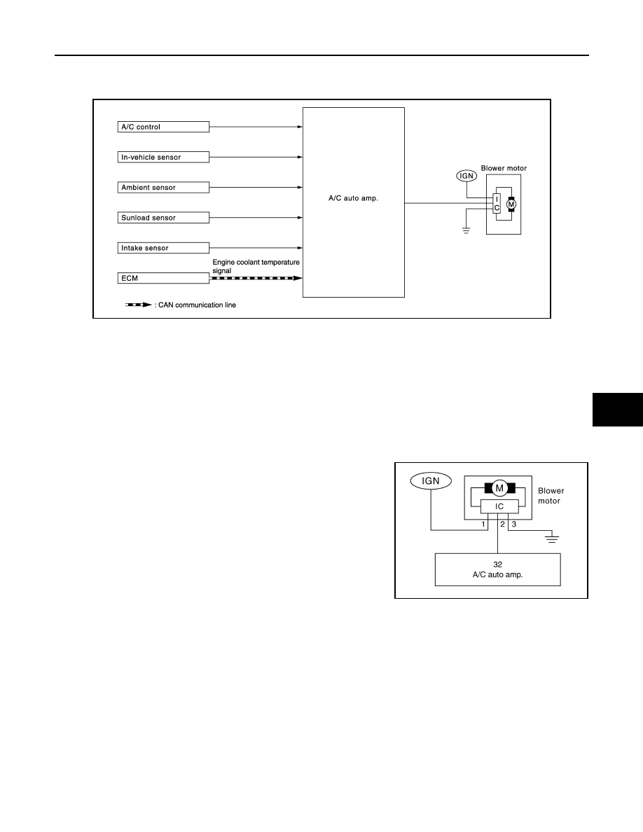
System Diagram
INFOID:0000000005514590
System Description
INFOID:0000000005514591
Blower speed is automatically controlled by the temperature setting, ambient temperature, in-vehicle tempera-
ture, intake temperature, amount of sunload and air mix door position.
By pressing the AUTO switch, the blower motor starts to gradually increase air flow volume.
When engine coolant temperature is low, the blower motor operation is delayed to prevent cool air from flow-
ing.
SYSTEM OPERATION
System operation
• For air flow, the manual selection (1-7) with the fan control dial has
priority.
• If the AUTO switch is pressed or if the DEF switch is pressed while
in the OFF condition, it changes to the automatic control by A/C
auto amp.
• When increasing the air flow, it changes the duty ratio of the blower
motor drive signal to prevent the air flow from suddenly increasing.
• There are the following types of air flow control: starting air flow
control, starting air flow control at low coolant temperature, starting
air flow control at high in-vehicle temperature, and air flow control
at actuator operation in addition to manual control, normal auto-
matic air flow control.
Normal automatic air flow control
• When the target temperature is set by the temperature control switch of A/C control, the A/C auto amp. per-
forms the calculation and decides the target according to the signal from each sensor.
• The A/C auto amp. changes the duty ratio of blower motor drive signal and controls the air flow continuously
so that the air flow becomes the target air flow.
• The minimum air flow will change according to the sunload when the air discharge outlet is VENT or B/L.
JSIIA1540GB
JSIIA0999ZZ