содержание .. 828 829 830 831 ..
Nissan Murano Z51. Manual - part 830
HA-36
< REMOVAL AND INSTALLATION >
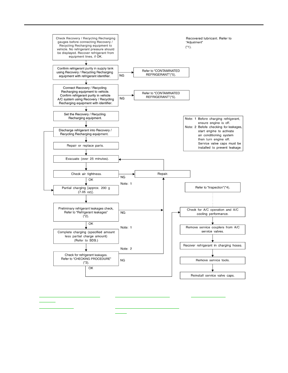
REFRIGERATION SYSTEM
*1
HA-25, "Maintenance of Lubricant
Quantity"
*2
*3
.
*4
*5
HA-14, "Working with HFC-134a (R-
134a)"
.
JSIIA0607GB
|
|
|
содержание .. 828 829 830 831 ..
HA-36 < REMOVAL AND INSTALLATION > REFRIGERATION SYSTEM *1 HA-25, "Maintenance of Lubricant *2 *3 . *4 *5 HA-14, "Working with HFC-134a (R- . JSIIA0607GB |