Nissan Murano Z51. Manual - part 769


  Главная      Nissan     Nissan Murano Z51 (2010 year) - Service Manual


поиск по сайту            


содержание   ..  767  768  769  770   ..


Nissan Murano Z51. Manual - part 769


EXT-10

< PRECAUTION >

PRECAUTIONS

5.

When the repair work is completed, re-connect both battery cables. With the brake pedal released, turn
the push-button ignition switch from ACC position to ON position, then to LOCK position. (The steering
wheel will lock when the push-button ignition switch is turned to LOCK position.)

6.

Perform self-diagnosis check of all control units using CONSULT-III.

FOR USA AND CANADA : Precaution for Procedure without Cowl Top Cover

INFOID:0000000005516264

When performing the procedure after removing cowl top cover, cover
the lower end of windshield with urethane, etc.

FOR USA AND CANADA : Precaution for Work

INFOID:0000000005516265

• After removing and installing the opening/closing parts, be sure to carry out fitting adjustments to check their

operation.

• Check the lubrication level, damage, and wear of each part. If necessary, grease or replace it.

EXCEPT FOR MEXICO

EXCEPT FOR MEXICO : Precaution for Supplemental Restraint System (SRS) "AIR 
BAG" and "SEAT BELT PRE-TENSIONER"

INFOID:0000000005716262

The Supplemental Restraint System such as “AIR BAG” and “SEAT BELT PRE-TENSIONER”, used along
with a front seat belt, helps to reduce the risk or severity of injury to the driver and front passenger for certain
types of collision. Information necessary to service the system safely is included in the “SRS AIR BAG” and
“SEAT BELT” of this Service Manual.

WARNING:

• To avoid rendering the SRS inoperative, which could increase the risk of personal injury or death in

the event of a collision which would result in air bag inflation, all maintenance must be performed by
an authorized NISSAN/INFINITI dealer.

• Improper maintenance, including incorrect removal and installation of the SRS, can lead to personal

injury caused by unintentional activation of the system. For removal of Spiral Cable and Air Bag
Module, see the “SRS AIR BAG”.

• Do not use electrical test equipment on any circuit related to the SRS unless instructed to in this

Service Manual. SRS wiring harnesses can be identified by yellow and/or orange harnesses or har-
ness connectors.

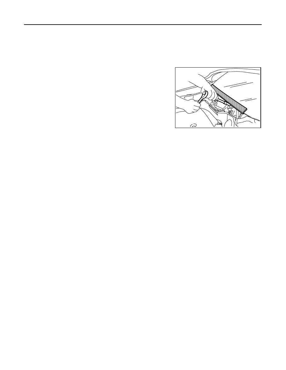
PRECAUTIONS WHEN USING POWER TOOLS (AIR OR ELECTRIC) AND HAMMERS

WARNING:

• When working near the Air Bag Diagnosis Sensor Unit or other Air Bag System sensors with the

ignition ON or engine running, DO NOT use air or electric power tools or strike near the sensor(s)
with a hammer. Heavy vibration could activate the sensor(s) and deploy the air bag(s), possibly
causing serious injury.

• When using air or electric power tools or hammers, always switch the ignition OFF, disconnect the

battery, and wait at least 3 minutes before performing any service.

EXCEPT FOR MEXICO : Precaution Necessary for Steering Wheel Rotation after Bat-
tery Disconnect

INFOID:0000000005716259

NOTE:
• Before removing and installing any control units, first turn the push-button ignition switch to the LOCK posi-

tion, then disconnect both battery cables.

PIIB3706J

PRECAUTIONS

EXT-11

< PRECAUTION >

C

D

E

F

G

H

I

J

L

M

A

B

EXT

N

O

P

• After finishing work, confirm that all control unit connectors are connected properly, then re-connect both

battery cables.

• Always use CONSULT-III to perform self-diagnosis as a part of each function inspection after finishing work.

If a DTC is detected, perform trouble diagnosis according to self-diagnosis results.

For vehicle with steering lock unit, if the battery is disconnected or discharged, the steering wheel will lock and
cannot be turned.
If turning the steering wheel is required with the battery disconnected or discharged, follow the operation pro-
cedure below before starting the repair operation.

OPERATION PROCEDURE

1.

Connect both battery cables.
NOTE:
Supply power using jumper cables if battery is discharged.

2.

Turn the push-button ignition switch to ACC position.
(At this time, the steering lock will be released.)

3.

Disconnect both battery cables. The steering lock will remain released with both battery cables discon-
nected and the steering wheel can be turned.

4.

Perform the necessary repair operation.

5.

When the repair work is completed, re-connect both battery cables. With the brake pedal released, turn
the push-button ignition switch from ACC position to ON position, then to LOCK position. (The steering
wheel will lock when the push-button ignition switch is turned to LOCK position.)

6.

Perform self-diagnosis check of all control units using CONSULT-III.

EXCEPT FOR MEXICO : Precaution for Procedure without Cowl Top Cover

INFOID:0000000005716260

When performing the procedure after removing cowl top cover, cover
the lower end of windshield with urethane, etc.

EXCEPT FOR MEXICO : Precaution for Work

INFOID:0000000005716261

• After removing and installing the opening/closing parts, be sure to carry out fitting adjustments to check their

operation.

• Check the lubrication level, damage, and wear of each part. If necessary, grease or replace it.

PIIB3706J

EXT-12

< PREPARATION >

PREPARATION

PREPARATION

PREPARATION

Special Service Tools

INFOID:0000000005516266

The actual shapes of Kent-Moore tools may differ from those of special service tools illustrated here.

Commercial Service Tools

INFOID:0000000005516267

Tool number

(Kent-Moore No.)

Tool name

Description

(J-39570)
Chassis ear

Locates the noise

(J-43980)
NISSAN Squeak and Rattle 
Kit

Repairs the cause of noise

SIIA0993E

SIIA0994E

Tool name

Description

Engine ear

Locates the noise

Remover tool

Removes clips, pawls and metal clips 

Power tool

SIIA0995E

PIIB7923J

PIIB1407E

FRONT BUMPER

EXT-13

< REMOVAL AND INSTALLATION >

C

D

E

F

G

H

I

J

L

M

A

B

EXT

N

O

P

REMOVAL AND INSTALLATION

FRONT BUMPER

Exploded View

INFOID:0000000005516268

JMKIA1961ZZ


содержание   ..  767  768  769  770   ..