Nissan Murano Z51. Manual - part 666


  Главная      Nissan     Nissan Murano Z51 (2010 year) - Service Manual


поиск по сайту            


содержание   ..  664  665  666  667   ..


Nissan Murano Z51. Manual - part 666


EM-136

< UNIT DISASSEMBLY AND ASSEMBLY >

CYLINDER BLOCK

2.

Install main bearing caps and main bearing beam, and tighten to the specified torque. Otherwise, cylinder
bores may be distorted in final assembly.

3.

Cut cylinder bores.
NOTE:
• When any cylinder needs boring, all other cylinders must also be bored.
• Do not cut too much out of cylinder bore at a time. Cut only 0.05 mm (0.0020 in) or so in diameter at a

time.

4.

Hone cylinders to obtain the specified piston to cylinder bore clearance.

5.

Measure finished cylinder bore for the out-of-round and taper.
NOTE:
Measurement should be done after cylinder bore cools down.

CRANKSHAFT MAIN JOURNAL DIAMETER

• Measure the outer diameter of crankshaft main journals with a micrometer.

• If out of the standard, measure the main bearing oil clearance. Then use undersize bearing. Refer to 

EM-

142, "Main Bearing"

.

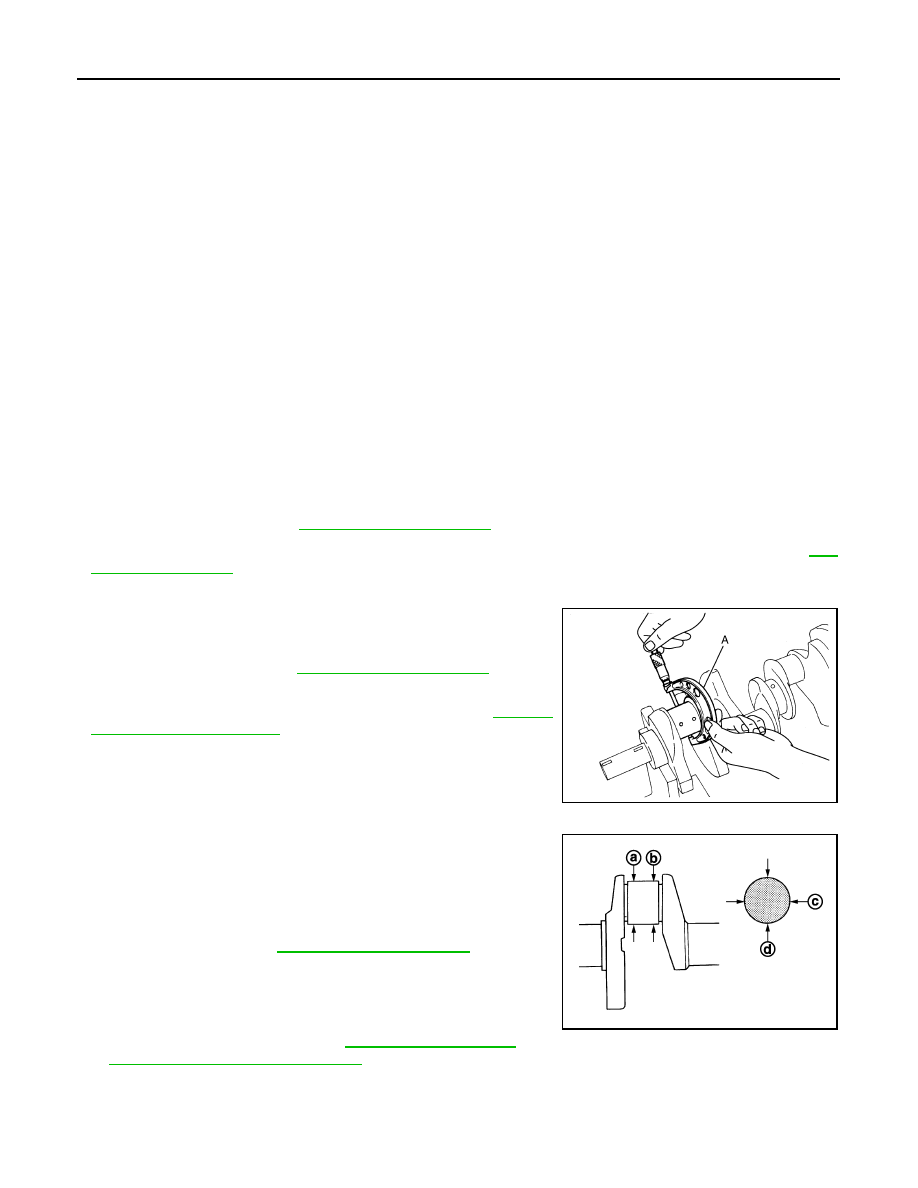
CRANKSHAFT PIN JOURNAL DIAMETER

• Measure the outer diameter of crankshaft pin journal with a

micrometer (A).

• If out of the standard, measure the connecting rod bearing oil

clearance. Then use undersize bearing. Refer to 

EM-141,

"Connecting Rod Bearing"

.

CRANKSHAFT OUT-OF-ROUND AND TAPER

• Measure the dimensions at four different points as shown in the

figure on each main journal and pin journal with a micrometer. 

• Out-of-round is indicated by the difference in the dimensions

between (d) and (c) at (a) and (b).

• Taper is indicated by the difference in the dimensions between.

• If the measured value exceeds the limit, correct or replace crank-

shaft.

• If corrected, measure the bearing oil clearance of the corrected

main journal and/or pin journal. Then select the main bearing and/
or connecting rod bearing. Refer to 

EM-142, "Main Bearing"

 and/

or 

EM-141, "Connecting Rod Bearing"

.

CRANKSHAFT RUNOUT 

• Place V-block on precise flat table, and support the journals on the both end of crankshaft.

Rebored size calculation: D = A + B – C

where,

A: Piston skirt diameter as measured

B: Piston to cylinder bore clearance (standard value)

C: Honing allowance 0.02 mm (0.0008 in)

D: Bored diameter

Standard

: Refer to 

EM-150, "Cylinder Block"

.

Standard

: Refer to 

EM-150, "Cylinder Block"

.

JPBIA0228ZZ

Limit

: Refer to 

EM-150, "Cylinder Block"

.

JPBIA0229ZZ

CYLINDER BLOCK

EM-137

< UNIT DISASSEMBLY AND ASSEMBLY >

C

D

E

F

G

H

I

J

K

L

M

A

EM

N

P

O

• Place a dial indicator straight up on the No. 3 journal.
• While rotating crankshaft, read the movement of the pointer on a

dial indicator. (Total indicator reading)

• If it exceeds the limit, replace crankshaft.

CONNECTING ROD BEARING OIL CLEARANCE

Method by Calculation

• Install connecting rod bearings (1) to connecting rod (2) and con-

necting rod cap, and tighten connecting rod bolts to the specified
torque. Refer to 

EM-122, "Disassembly and Assembly"

 for the

tightening procedure.

• Measure the inner diameter of connecting rod bearing with an

inside micrometer.

(Oil clearance) = (Connecting rod bearing inner diameter) – (Crank-
shaft pin journal diameter)

• If the calculated value exceeds the limit, select proper connecting

rod bearing according to connecting rod big end diameter and crankshaft pin journal diameter to obtain the
specified bearing oil clearance. Refer to 

EM-141, "Connecting Rod Bearing"

.

Method of Using Plastigage

• Remove oil and dust on crankshaft pin journal and the surfaces of each bearing completely. 
• Cut a plastigage slightly shorter than the bearing width, and place it in crankshaft axial direction, avoiding oil

holes.

• Install connecting rod bearings to connecting rod and connecting rod bearing cap, and tighten connecting

rod bolts to the specified torque. Refer to 

EM-122, "Disassembly and Assembly"

 for the tightening proce-

dure.

CAUTION:

Never rotate crankshaft.

• Remove connecting rod bearing cap and bearings, and using the

scale on the plastigage bag, measure the plastigage width.
NOTE:
The procedure when the measured value exceeds the limit is
same as that described in the “Method by Calculation”.

MAIN BEARING OIL CLEARANCE

Method by Calculation

Standard and limit

: Refer to 

EM-150, "Cylinder Block"

.

SEM346D

Standard and limit

: Refer to 

EM-154, 

"Connecting Rod Bearing"

.

JPBIA0230ZZ

JPBIA0231ZZ

EM-138

< UNIT DISASSEMBLY AND ASSEMBLY >

CYLINDER BLOCK

• Install main bearings (3) to cylinder block (1) and main bearing

caps (2), and main bearing cap bolts with main bearing beam to
the specified torque. Refer to 

EM-122, "Disassembly and Assem-

bly"

 for the tightening procedure.

• Measure the inner diameter of main bearing with a bore gauge.
(Oil clearance) = (Main bearing inner diameter) – (Crankshaft main
journal diameter)

• If the calculated value exceeds the limit, select proper main bear-

ing according to main bearing inner diameter and crankshaft main
journal diameter to obtain the specified bearing oil clearance.
Refer to 

EM-142, "Main Bearing"

.

Method of Using Plastigage

• Remove engine oil and dust on crankshaft journal and the surfaces of each bearing completely. 
• Cut a plastigage slightly shorter than the bearing width, and place it in crankshaft axial direction, avoiding oil

holes.

• Install main bearing to cylinder block and main bearing caps, and tighten main bearing cap bolts with main

bearing beam to the specified torque. Refer to 

EM-122, "Disassembly and Assembly"

 for the tightening pro-

cedure.

CAUTION:

Never rotate crankshaft.

• Remove main bearing caps and bearings, and using the scale on

the plastigage bag, measure the plastigage width. 
NOTE:
The procedure when the measured value exceeds the limit is
same as that described in the “Method by Calculation”.

MAIN BEARING CRUSH HEIGHT

• When main bearing cap is removed after being tightened to the

specified torque with main bearings (1) installed, the tip end of
bearing must protrude. Refer to 

EM-122, "Disassembly and

Assembly"

 for the tightening procedure.

• If the standard is not met, replace main bearings.

CONNECTING ROD BEARING CRUSH HEIGHT

• When connecting rod bearing cap is removed after being tightened

to the specified torque with connecting rod bearings (1) installed,
the tip end of bearing must protrude. Refer to 

EM-122, "Disassem-

bly and Assembly"

 for the tightening procedure.

• If the standard is not met, replace connecting rod bearings.

Standard and limit

: Refer to 

EM-153, "Main Bearing"

.

JPBIA0232ZZ

JPBIA0231ZZ

A

: Crush height

Standard

: There must be crush height.

JPBIA0233ZZ

A

: Crush height

Standard

: There must be crush height.

JPBIA0233ZZ

CYLINDER BLOCK

EM-139

< UNIT DISASSEMBLY AND ASSEMBLY >

C

D

E

F

G

H

I

J

K

L

M

A

EM

N

P

O

MAIN BEARING CAP BOLT OUTER DIAMETER

• Measure the outer diameters (c), (d) at two positions as shown in

the figure.

• If reduction appears in (a) range, regard it (c).

• If it exceeds the limit (large difference in dimensions), replace main

bearing cap bolt with new one.

CONNECTING ROD BOLT OUTER DIAMETER

• Measure the outer diameter (d) at position shown in the figure.
• If the reduction appears in a position other than (d), regard it as (d).

• When (d) exceeds the limit (when it becomes thinner), replace

connecting rod bolt with new one.

DRIVE PLATE

• Check drive plate and signal plate for deformation or damage.

CAUTION:

• Never disassemble drive plate.
• Never place drive plate with signal plate facing down.
• When handling signal plate, take care not to damage or

scratch it. 

• Handle signal plate in a manner that prevents it from becom-

ing magnetized.

• If anything is found, replace drive plate.

OIL JET

• Check nozzle for deformation and damage.
• Blow compressed air from nozzle, and check for clogs.
• If it is not satisfied, clean or replace oil jet.

OIL JET RELIEF VALVE

• Using a clean plastic stick, press check valve in oil jet relief valve.

Check that valve moves smoothly with proper reaction force.

• If it is not satisfied, replace oil jet relief valve.

a

: 20 mm (0.79 in)

b

: 30 mm (1.18 in)

e

: 10 mm (0.39 in)

Limit [(d) – (c)]

: 0.11 mm (0.0043 in)

JPBIA0234ZZ

Standard 

: 7.90 - 8.00 mm (0.3110 - 0.3150 in)

Limit

: 7.75 mm (0.3051 in)

PBIC0912E

JPBIA0192ZZ

EMU0468D


содержание   ..  664  665  666  667   ..