Nissan Murano Z51. Manual - part 665


  Главная      Nissan     Nissan Murano Z51 (2010 year) - Service Manual


поиск по сайту            


содержание   ..  663  664  665  666   ..


Nissan Murano Z51. Manual - part 665


EM-132

< UNIT DISASSEMBLY AND ASSEMBLY >

CYLINDER BLOCK

• Piston pin (piston pin hole) grade is provided only for the parts installed at the plant. For service parts, no

piston pin grades can be selected. (Only “0” grade is available.)

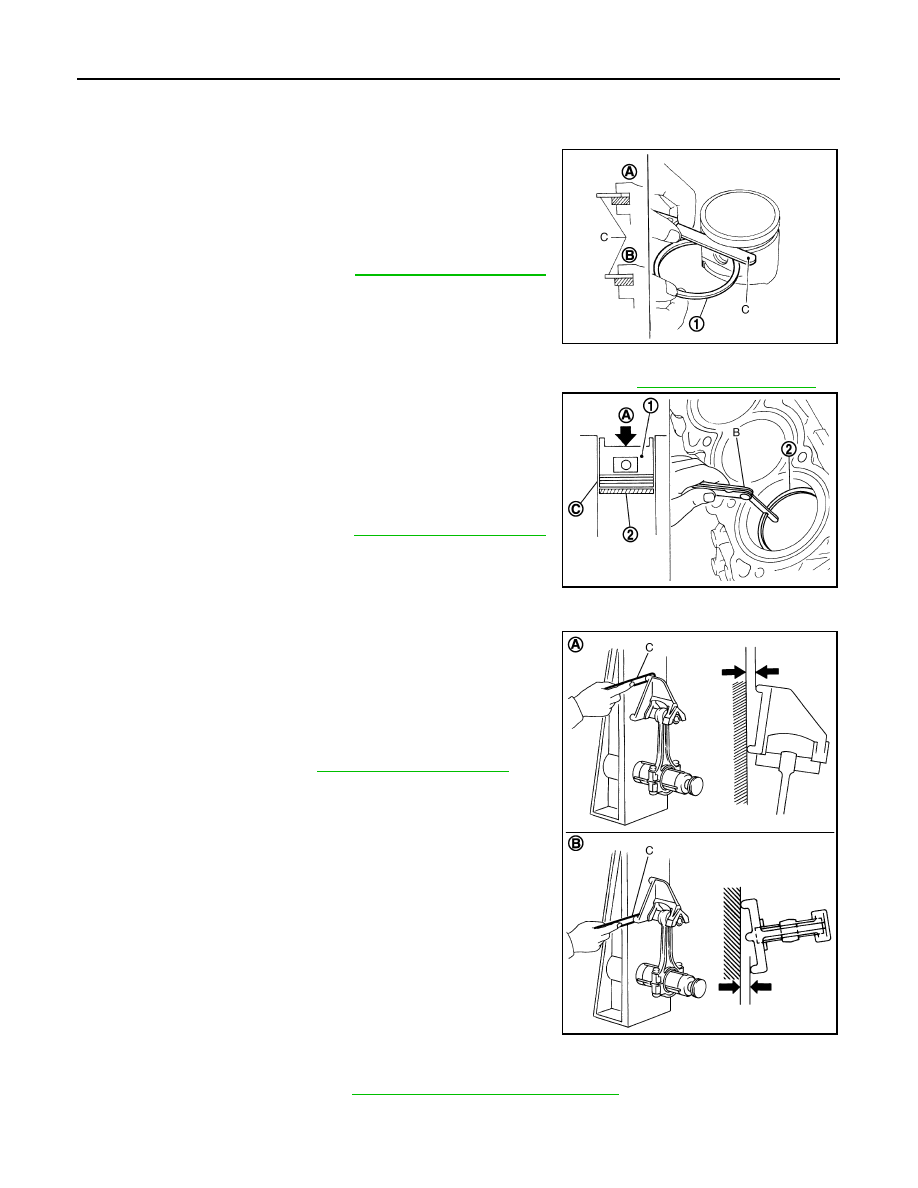
PISTON RING SIDE CLEARANCE

• Measure the side clearance of piston ring (1) and piston ring

groove with a feeler gauge (C).

• If the measured value exceeds the limit, replace piston ring, and

measure again. If it still exceeds the limit, replace piston also.

PISTON RING END GAP

• Check that the cylinder bore inner diameter is within the specification. Refer to 

EM-150, "Cylinder Block"

.

• Lubricate with new engine oil to piston (1) and piston ring (2), and

then insert piston ring until middle of cylinder with piston, and mea-
sure the piston ring end gap with a feeler gauge (B).

• If the measured value exceeds the limit, replace piston ring, and

measure again. If it still exceeds the limit, rebore cylinder and use
oversize piston and piston rings.

CONNECTING ROD BEND AND TORSION

• Check with a connecting rod aligner.

• If it exceeds the limit, replace connecting rod assembly.

CONNECTING ROD BIG END DIAMETER

• Install connecting rod bearing cap without installing connecting rod bearing, and tightening connecting rod

bolts to the specified torque. Refer to 

EM-122, "Disassembly and Assembly"

 for the tightening procedure.

A

:  NG

B

:  OK

Standard and limit

: Refer to 

EM-150, "Cylinder Block"

.

JPBIA0219ZZ

A

: Press-fit

C

: Measuring point

Standard and limit

: Refer to 

EM-150, "Cylinder Block"

.

JPBIA0220ZZ

A

:  Bend

B

:  Torsion

C

: Feeler gauge

Bend limit

: Refer to 

EM-150, "Cylinder Block"

.

Torsion limit

JPBIA0221ZZ

CYLINDER BLOCK

EM-133

< UNIT DISASSEMBLY AND ASSEMBLY >

C

D

E

F

G

H

I

J

K

L

M

A

EM

N

P

O

• Measure the inner diameter of connecting rod big end with an

inside micrometer.

• If out of the standard, replace connecting rod assembly.

CONNECTING ROD BUSHING OIL CLEARANCE

Connecting Rod Bushing Inner Diameter

Measure the inner diameter of connecting rod bushing with an inside
micrometer (A).

Piston Pin Outer Diameter

Measure the outer diameter of piston pin with a micrometer (A).

Connecting Rod Bushing Oil Clearance

(Connecting rod bushing oil clearance) = (Connecting rod bushing inner diameter) – (Piston pin outer diame-
ter)

• If the calculated value exceeds the limit, replace connecting rod assembly and/or piston and piston pin

assembly.

• If replacing piston and piston pin assembly, refer to 

EM-140, "Description"

.

• If replacing connecting rod assembly, refer to 

EM-141,

"Connecting Rod Bearing"

 to select the connecting rod bearing.

1

: Connecting rod

Standard

: Refer to 

EM-150, "Cylinder Block"

.

JPBIA0222ZZ

Standard

: Refer to 

EM-150, "Cylinder Block"

.

JPBIA0223ZZ

Standard

: Refer to 

EM-150, "Cylinder Block"

.

JPBIA0218ZZ

Standard and limit

: Refer to 

EM-150, "Cylinder Block"

.

A

:  Sample  codes

B

: Bearing stopper groove

C

: Small-end diameter grade

D

: Standard stamp

E

: Weight grade

F

: Cylinder No.

G

: Management code

JPBIA0208ZZ

EM-134

< UNIT DISASSEMBLY AND ASSEMBLY >

CYLINDER BLOCK

Factory installed parts grading:

• Service parts apply only to grade “0”.

Unit: mm (in)

*: After installing in connecting rod

CYLINDER BLOCK DISTORTION

• Using a scraper, remove gasket on the cylinder block surface, and also remove engine oil, scale, carbon, or

other contamination. 

CAUTION:

Be careful not to allow gasket flakes to enter engine oil or engine coolant passages.

• Measure the distortion on the cylinder block upper face at some

different points in six directions (C), (D), (E), (F), (G), and (H) with a
straightedge (A) and a feeler gauge (B).

• If it exceeds the limit, replace cylinder block.

MAIN BEARING HOUSING INNER DIAMETER

• Install main bearing caps and main bearing beam without installing main bearings, and tighten main bearing

cap bolts to the specified torque. Refer to 

EM-122, "Disassembly and Assembly"

 for the tightening proce-

dure.

• Measure the inner diameter of main bearing housing with a bore

gauge.

• If out of the standard, replace cylinder block (1) and main bearing

caps (2) as assembly.
NOTE:
Cylinder block cannot be replaced as a single part, because it is
machined together with main bearing caps.

H

: Front mark

I

: Management code

A

: Piston grade number

B

:  Front  mark

C

: Piston pin grade number

D

: Identification code

JPBIA2199ZZ

Grade

0

1

Connecting rod bushing inner diameter *

22.000 - 22.006

(0.8661 - 0.8664)

22.006 - 22.012

(0.8664 - 0.8666)

Piston pin hole diameter

21.993 - 21.999

(0.8659 - 0.8661)

21.999 - 22. 005

(0.8661 - 0.8663)

Piston pin outer diameter

21.989 - 21.995

(0.8657 - 0.8659)

21.995 - 22.001

(0.8659 - 0.8662)

Limit

: Refer to 

EM-150, "Cylinder Block"

.

JPBIA0224ZZ

Standard

: Refer to 

EM-150, "Cylinder Block"

.

JPBIA0225ZZ

CYLINDER BLOCK

EM-135

< UNIT DISASSEMBLY AND ASSEMBLY >

C

D

E

F

G

H

I

J

K

L

M

A

EM

N

P

O

PISTON TO CYLINDER BORE CLEARANCE

Cylinder Bore inner Diameter 

• Using a bore gauge, measure cylinder bore for wear, out-of-round

and taper at six different points on each cylinder. [(A) and (B) direc-
tions at (C), (D) and (E)] is in longitudinal direction of engine.

• If the measured value exceeds the limit, or if there are scratches

and/or seizure on the cylinder inner wall, hone or rebore the inner
wall. 

• Oversize piston is provided. When using oversize piston, rebore

cylinder so that the clearance of the piston to cylinder bore satis-
fies the standard.

CAUTION:

When using oversize piston, use oversize pistons for all cylin-
ders with oversize piston rings.

Piston Skirt Diameter

Measure the outer diameter of piston skirt with a micrometer (A).

Piston-to-Cylinder Bore Clearance

Calculate by piston skirt diameter and cylinder bore inner diameter
[direction (B), position (D)].

(Clearance) = (Cylinder bore inner diameter) – (Piston skirt diame-
ter).

• If the calculated value exceeds the limit, replace piston and piston pin assembly. Refer to 

EM-140, "Piston"

.

Reboring Cylinder Bore

1.

Cylinder bore size is determined by adding piston to cylinder bore clearance to piston skirt diameter.

f

: 10 mm (0.39 in)

g

: 60 mm (2.36 in)

h

: 120 mm (4.72 in)

Standard and limit

: Refer to 

EM-150, "Cylinder Block"

.

JPBIA0226ZZ

Oversize (O/S)

: 0.2 mm (0.008 in)

SEM843E

Measure point 

: Refer to 

EM-150, "Cylinder Block"

.

Standard

JPBIA0227ZZ

A

:  Direction  A

C

: Position C

E

: Position E

f

: 10 mm (0.39 in)

g

: 60 mm (2.36 in)

h

: 120 mm (4.72 in)

Standard and limit

: Refer to 

EM-150, "Cylinder Block"

.

JPBIA0226ZZ


содержание   ..  663  664  665  666   ..