содержание .. 650 651 652 653 ..
Nissan Murano Z51. Manual - part 652
EM-80
< UNIT REMOVAL AND INSTALLATION >
ENGINE ASSEMBLY
a.
Tighten the bolt No. 3 as shown in the figure. (temporarily)
b.
Tighten the bolts in numerical order as shown in the figure.
(specified torque)
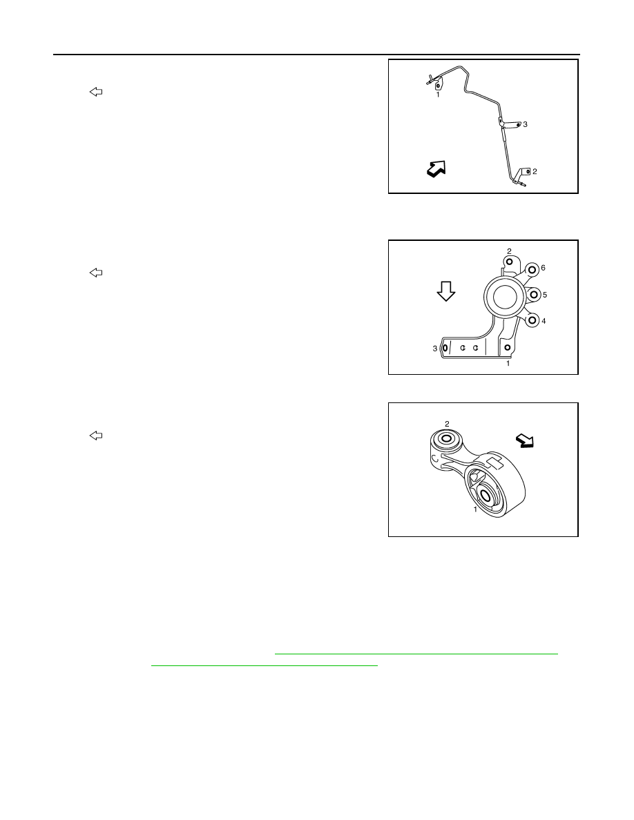
Installation
1.
Install the engine mounting insulator (RH) as follows:
a.
Tighten the bolt No. 1 as shown in the figure. (temporarily)
b.
Tighten the bolts No. 2, 3 in numerical order as shown in the fig-
ure. (specified torque)
c.
Tighten the bolt No. 1 as shown in the figure. (specified torque)
d.
Tighten the bolts No. 4, 5, 6 in numerical order as shown in the
figure. (specified torque)
2.
Install the upper torque rod as follows:
a.
Tighten the bolt No. 2 as shown in the figure. (temporarily)
b.
Tighten the bolts in numerical order as shown in the figure.
(specified torque)
2WD : Inspection
INFOID:0000000005515952
INSPECTION AFTER INSTALLATION
Inspection for Leakage
The following are procedures for checking fluids leakage, lubricates leakage, and exhaust gases leakage.
• Before starting engine, check oil/fluid levels including engine coolant and engine oil. If less than required
quantity, fill to the specified level. Refer to
MA-15, "FOR NORTH AMERICA : Fluids and Lubricants"
(for
North America) or
MA-16, "FOR MEXICO : Fluids and Lubricants"
(for Mexico).
• Use procedure below to check for fuel leakage.
- Turn ignition switch “ON” (with engine stopped). With fuel pressure applied to fuel piping, check for fuel leak-
age at connection points.
- Start engine. With engine speed increased, check again for fuel leakage at connection points.
• Run engine to check for unusual noise and vibration.
• Warm up engine thoroughly to check there is no leakage of fuel, exhaust gases, or any oil/fluids including
engine oil and engine coolant.
• Bleed air from lines and hoses of applicable lines, such as in cooling system.
• After cooling down engine, again check oil/fluid levels including engine oil and engine coolant. Refill to the
specified level, if necessary.
: Engine front
JPBIA1741ZZ
: Vehicle front
JPBIA1742ZZ
: Vehicle front
JPBIA1743ZZ