содержание .. 648 649 650 651 ..
Nissan Murano Z51. Manual - part 650
EM-72
< UNIT REMOVAL AND INSTALLATION >
ENGINE ASSEMBLY
UNIT REMOVAL AND INSTALLATION
ENGINE ASSEMBLY
2WD
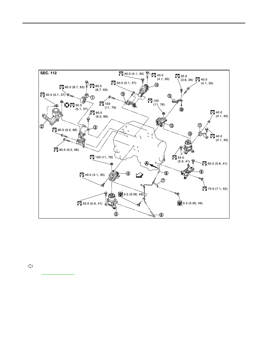
2WD : Exploded View
INFOID:0000000005515950
Without Vacuum Tube (Rear) Models
JPBIA2769GB
1.
Upper torque rod
2.
Engine mounting insulator (RH)
3.
Engine mounting bracket (RH)
4.
Engine mounting bracket (front)
5.
Engine mounting insulator (front)
6.
Vacuum hose
7.
Vacuum tube (front)
8.
Vacuum hose
9.
Engine mounting insulator (LH)
10.
Engine mounting insulator (rear)
11. Engine mounting stay (rear)
12. Engine mounting bracket (rear)
13.
Gusset
14. Rear torque rod
15. Rear torque rod bracket
A.
To electronic controlled engine mount
control solenoid valve
B.
To transaxle
: Vehicle front
Refer to
for symbols in the figure.