содержание .. 552 553 554 555 ..
Nissan Murano Z51. Manual - part 554
EC-224
< DTC/CIRCUIT DIAGNOSIS >
[VQ35DE]
P0171, P0174 FUEL INJECTION SYSTEM FUNCTION
5.
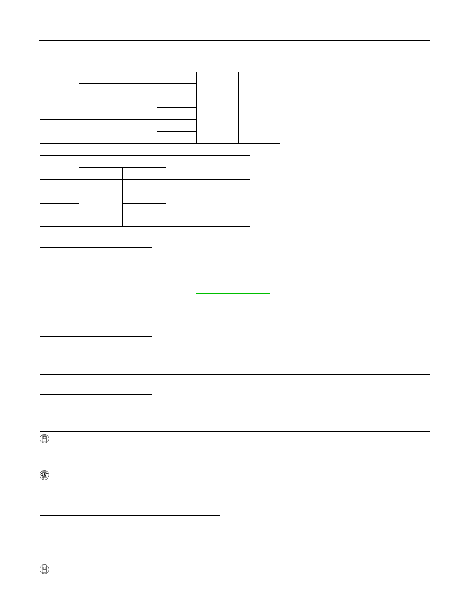
Check the continuity between A/F sensor 1 harness connector and ground, or ECM harness connector
and ground.
6.
Also check harness for short to power.
Is the inspection result normal?
YES
>> GO TO 4.
NO
>> Repair open circuit, short to ground or short to power in harness or connectors.
4.
CHECK FUEL PRESSURE
1.
Release fuel pressure to zero. Refer to
2.
Install fuel pressure gauge kit [SST (J-44321)] and check fuel pressure. Refer to
Is the inspection result normal?
YES
>> GO TO 6.
NO
>> GO TO 5.
5.
DETECT MALFUNCTIONING PART
Check fuel hoses and fuel tubes for clogging.
Is the inspection result normal?
YES
>> Replace “fuel filter and fuel pump assembly”.
NO
>> Repair or replace malfunctioning part.
6.
CHECK MASS AIR FLOW SENSOR
With CONSULT-III
1.
Install all removed parts.
2.
Check “MASS AIR FLOW” in “DATA MONITOR” mode with CONSULT-III.
For specification, refer to
EC-536, "Mass Air Flow Sensor"
With GST
1.
Install all removed parts.
2.
Check mass air flow sensor signal in Service $01 with GST.
For specification, refer to
EC-536, "Mass Air Flow Sensor"
Is the measurement value within the specification?
YES
>> GO TO 7.
NO
>> Check connectors for rusted terminals or loose connections in the mass air flow sensor circuit or
ground. Refer to
7.
CHECK FUNCTION OF FUEL INJECTOR
With CONSULT-III
1.
Start engine.
DTC
A/F sensor 1
Ground
Continuity
Bank
Connector
Terminal
P0171
1
F27
1
Ground
Not existed
2
P0174
2
F64
1
2
DTC
ECM
Ground
Continuity
Connector
Terminal
P0171
F8
45
Ground
Not existed
49
P0174
53
57
At idling: Approximately 350 kPa (3.57 kg/cm
2
, 51 psi)